My hamlet of residence’s annual “snow storm” blew in this last week with a fury not seen since 2015:
With the snowpocalypse outside, I stayed inside working on the Mustang’s dash.
I started with the instrument cluster that I’d gotten out a couple of weeks ago:
In order to install the cluster, I had to first set it on top of the steering column and attach the speedometer cable:
…and the gauge cluster electrical connection:
With the cluster’s accessories attached, I did a quick electrical sanity check. I disconnected the leads from the oil pressure, temperature and the fuel level sending units and grounded them to the chassis. After turning the key to accessory, all three gauges pegged high as they should have. I then flipped the shop lights off and and turned the Mustang’s headlights on. Much to my delight, the gauge cluster burst to life with a brilliant blue hue:
The red Mustang you see in the image above is the high-beam head light indicator. As a kid, I played with that light almost as much as I played with the hood scoop lights and it gave me warm fuzzies to know that I can play with it again as much as I’d like.
With everything checked out electrically, it was a fairly simple matter to attach the gauge cluster to the car:
At that point, there was one small niggle that I needed to take care of before I could proceed. Somehow, in the year and a half since I put the lower dash back together, the custom radio bezel I purchased that allowed me to use a modern radio got itself a little warped:
It wasn’t a huge deal and was barely visible, but I knew it was there and it would have bothered me. If I was going to fix the warping, I needed to do so before I installed the dash and lost access.
My fix for the problem involved slightly modifying a couple of these L-Brackets:
so I could hook them behind the bezel, pull the bezel forward and then fix everything in place by attaching the brackets to a couple of very conveniently located holes in the lower dash:
Problem solved.
And then it was time to open the big box:
I’ve been waiting to open this box since it first arrived at my door over two years ago. Inside the box was a built-from-original-Ford-tooling dash pad for the Mustang in beautiful condition:
Compared to the Mustang’s original dash, I think we’ve managed an upgrade:
Before I could install the dash, I needed to accessorize it a bit. I started by installing the dual-coil speaker that will allow me to have some semblance of front stereo sound from my radio:
I then turned my attention to the passenger side dash bezel:
This plastic part was original to the car and while it cleaned up well after being painted, it still needed a little attention before it could be installed:
I then simply poured the powder base in, jiggled it a bit so it would settle and applied the bonding glue. In seconds, it had cured and all I needed to do was drill out my hole to have myself a fixed mounting point. I love this stuff:
It looks like these dash bezels began being reproduced starting some time last year. While the new one might not be as fragile, I think my restored one looks great and I had no problems attaching it to the dash pad for installation.
With the speaker and the dash bezel attached to the dash, I got out the outer dash moldings and the steering column trim that would go on after everything was installed topside:
With everything ready to go, I moved the dash pad and its accessories over to the car, attached the speaker wires and then proceeded to successfully screw everything in.
Really.
I’m not kidding.
Everything just worked.
Nothing went wrong.
Seriously, after about 45 minutes of making sure everything was lined up and all the screws were started, the Mustang’s interior went from a metal box motif to one that resembles an actual car.
The worst thing I can say about this installation was that the top adjustment bolts on the lower dash that attach to the A Pillar are a pain to tighten after the dash pad is installed.
At that point, I called it a day and headed up to the house with a big grin on my face.
In software terms, an “Easter Egg” is a hidden feature of a program that must be hunted for and/or discovered by users. The term has its origins in a game designed for my first gaming console, the Atari 2600:
The author of the Atari 2600 game Adventure, prevented by company policy to credit himself in the game, inserted special code into the program that allowed the users to see a hidden, undocumented credits page if they performed a series of seemingly random tasks.
Upon discovery, the management of Atari decided that the fan reaction to the page was very positive. In fact, people were playing their games longer “hunting” for other undocumented features. The term “Easter Egg” was born describing the behavior of users hunting for these features.
Since that time, it’s become tradition in many software products to include Easter Eggs. Microsoft Excel at one point had a flight simulator credits page. To this day, Google still has their do a barrel roll and Zerg rush Easter Eggs active on their site.
This week, I decided to create a little Easter Egg of my own for whomever owns the Mustang after me.
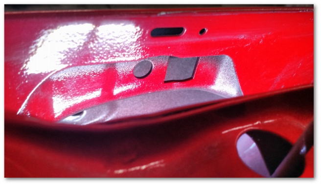
It started with wondering what this connector on the lower dash wiring harness was for:
A quick check of the wiring diagram for the Mustang showed that this connector (and a similar one on the driver’s side) were for optional dash mounted courtesy lights. These plugs were wired into the same circuit as the dome light and (when ordered) would attach to a wiring harness, bracket and light that would add additional illumination to the floor boards of the car.
Sure enough, a quick check with the multi-meter showed that when the doors were opened the plugs were provided with 12 volts. Nifty.
I quickly discovered with my research that while the courtesy light brackets and wiring harnesses are available used, purchasing the entire setup would run over 50 dollars – not including the lights I would have to buy. I couldn’t justify it.
As it so happens, I have electrical connectors that could plug into that socket. I have lots and lots of extra LED bulbs. I have wire. All I needed to create my own courtesy lighting was the sockets and something to mount them on.
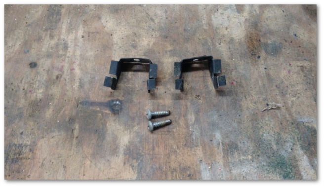
A seven dollar trip to AutoZone netted me the requisite sockets:
And a three dollar trip to the dollar store netted me the “brackets” to mount them:
Now for the most part, I’ve tried to keep the Mustang fairly original. I use the correct fasteners whenever possible and as a general rule I’ve kept my modifications subtle. In this case though, I couldn’t help myself. All of this mounts under the dash so no one will ever see it unless they’re in there working on something. I find the thought of somebody way down the line getting under the dash and finding….spoons…. irrationally funny.
To build my Easter Egg for the next owner of the Mustang, I started with some proof of concept wiring:
Opening the door yielded a satisfactorily illuminated result:
With the electrical worked out, it was time to move on to the mechanical. I drilled small pilot holes in the center of the ladles and used my rotary file to create a hole:
This hole was sized just right for the mounting clips on the socket to seat and solidly attach the fixture:
After adding a connector to the end of the socket’s wire, it was time to mount my “courtesy lights” onto the lower dash:
And give them a try:
Easter Egg success!
For now, I’m using blue LED’s for the under dash lights. I like the look and it complements the blue I have everywhere else in the dash lighting. In the future, if I want to change this to white or amber (or for that matter a different shade of blue), I have the lights on hand to do that too.
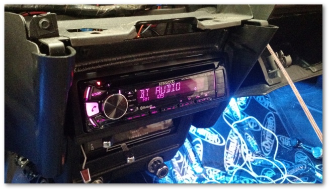
Having had my fun for the day, it was time to start getting down to real work. I began by taking my radio out of its box and reviewing its wiring diagram:
It took a little bit of futzing to get the radio to mount correctly, but after a short time I had it installed and playing music out of the single speaker I attached to it for testing:
I even routed the radio’s hands-free-calling microphone wire up through the A-pillars to the roof:
I will probably never use that feature of the radio, but with the car apart it was easy to install and would have been silly to leave unattached.
The last piece of the lower dash wiring I hooked up was the electric choke. With the choke hooked up, the lower dash wiring was complete:
With the lower dash wiring harness finished, it was time to start on the trunk wiring harness:
This harness drives the tail lights, rear running lights, reverse lights, dome light and the gas gauge. Thankfully, all of these sockets are out in the open and easy to plug into.
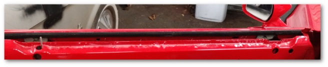
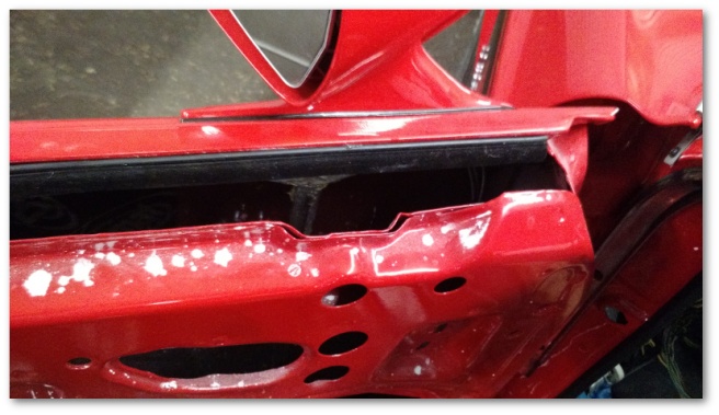
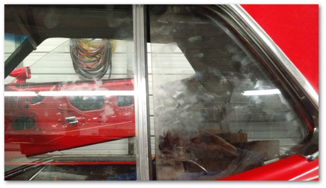
The trunk harness (and the speaker wires I ran along with it) connects to the lower dash wiring harness on the driver’s side and then runs along the rocker to the quarter panel.
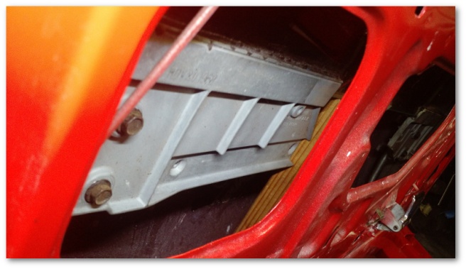
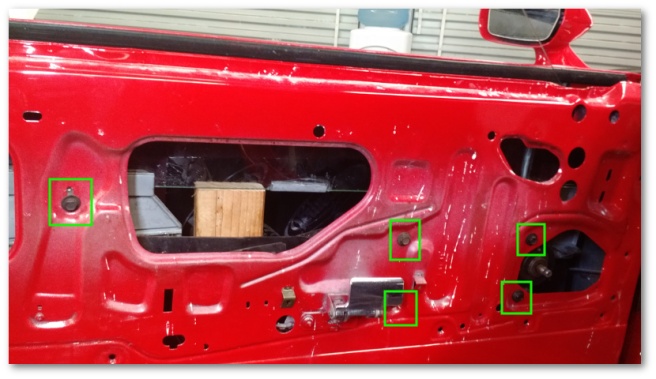
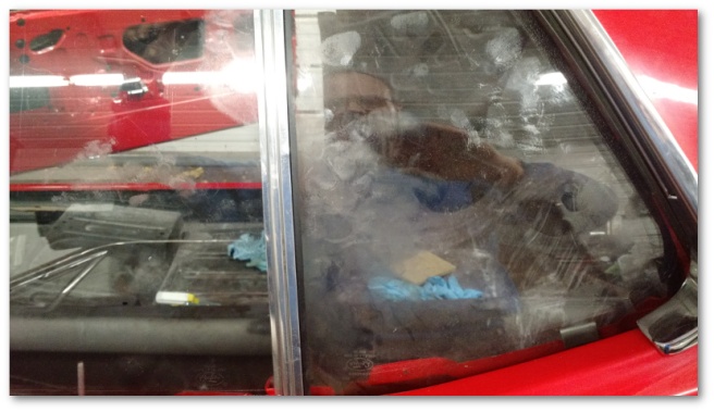
It then loops behind the quarter panel window bracket, over the wheel house and into the trunk. From there it gets routed like so:
Here’s the same picture with the wiring (red), clips (yellow) and ground connectors (purple) highlighted:
When I first got the Mustang, there was an intermittent grounding issue in the tail lights. As I was researching how to route and install the trunk wiring harness, I discovered that the harness’ ground connector is supposed to attach to the tail panel’s trunk brace. However, Mr. Previous Owner had attached it to the hose clamps on the rubber gas filler tube. Rubber, as you may know is rather a poor conductor of electricity and you can imagine the effectiveness of the ground clamp as previously installed.
With everything hooked up, I turned every possible light on to bask in the glory of my completed trunk wiring. Aaaaand then discovered this:
For the record, all three of those bars are supposed to be lit up as was the case on the driver’s side:
Weirdly enough, it was just the running lights. The flashers and brake lights worked great. That meant that the Mustang’s wiring was working fine and the problem had to be internal to the tail lights themselves.
I purchased these lights about two years ago so if there was a warranty it would have likely expired by now. Replacing the light was of course possible, but would have cost over 70 dollars. I wasn’t keen on spending that.
Off came the tail light and it was taken apart on the bench. I figured maybe I bent/broke one of the external wires that feed the bank of LED’s that weren’t lighting up. Unfortunately, once the assembly was out of the car and on the bench it worked just fine. Worse, I could not get it to break by wiggling the wires.
Hmmmmm….
I carefully put everything back together and mounted the assembly back on the car. It worked for a couple of minutes and then turned off again. AAAAAAARRRRRGGGG!!!!
Everything came apart again. This time, my “bench” was the trunk of the car so I could keep it connected to the wiring harness. At first, the bank of LED’s stayed off which was good because it allowed me to recreate the problem. However, at one point I walked away to grab a tool and came back to a fully-illuminated tail light.
NOTHING had changed, but the light was now working properly.
At that point, I took a small break and noodled a bit. Here was a summary of my situation:
The bank of LED’s either worked or did not work – there was no in between half-way illumination
The problem was NOT the external wires feeding the bank – I could move those around without impacting the functionality regardless of whether or not the lights were on or not
The Mustang’s trunk wiring harness was working correctly
The problem had to be inside the sealed unit itself
After my noodling, I had a theory. The LED’s had worked on my bench and briefly when relocated to the car. After being in the car for a short time, the LED’s stopped working. What was the difference between my work bench and the trunk?
The tail lights are nothing more than a bunch of LED’s with some circuitry on a printed circuit board. These electrical components are soldered to the board just like the components in your computer. If one of the solder joints was just a leeeeeeetle off, it could create exactly the problem I was seeing. A little heat and the solder joint would get warm enough to make a solid electrical connection. Once the heat was removed, the solder joint would return to doing nothing, similar to how I behave when it’s cold outside.
To test my theory, I plugged the lights in, made sure the broken bank was still not illuminating and then grabbed my heat gun. The results (wait for it) were rather conclusive:
So… theory confirmed. Now what?
I spent four years in college to become an electrical engineer. While I can’t say I’ve ever used that education in any application related to my career, I can say that still to this day if something is basic electrical and broken I can fix it.
So, I tore the tail light apart. I used my heat gun to gently warm up and remove the resin that sealed the broken board in.
Guess what I found loose in its socket?
According to my reading of the circuit board, this is the resister that steps down the 12 volts provided by the Mustang’s trunk wiring harness’ parking light wire to a lower voltage. This lower voltage causes the LED’s to illuminate less brightly than if they were powered by the full 12 volts.
It was a simple test to jump the resister and the old solder connection to see if the lights came on. Sure enough, they did. A quick re-solder of the joint and the fix was made (hopefully) permanent.
This left me with a fixed circuit board that was now fully exposed to the elements. Eventually, this would have likely caused the board to corrode and break in other areas. Thankfully (and rather unbelievably) I had just the thing to re-seal the unit:
I had purchased this resin back when I glued the windows back to their brackets. I didn’t use it for the windows themselves, but rather for the little metal bumper shield that attaches to the bottom of the window and protects it from the rubber bump stop.
As it turns out, this resin is also clear, self leveling, water proof and was sitting on my shelf right where I left it a year and a half ago. I had just enough too:
Today, everything went back together again. And this time, everything worked:
At this point, the only thing left to connect to the electrical system is the gauge cluster:
That unit is currently sitting on my work bench eagerly awaiting next week…
Early last week, my order of (very nice) amber turn signal LEDs:
came in and I was able to get my turn signal and parking light systems working together correctly. These lights are unbelievably bright. After I replaced the first lamp, I tested the system and these LEDs are easily twice as bright as the amber LEDs I’d originally been using. If you have the means, I highly recommend picking some up.
The same box that brought me the LEDs also brought me my patch wiring for the ignition switch light pigtail:
I was a little apprehensive about buying this part used, but it arrived in perfect shape. I spliced it into my wiring harness, plugged the light in and ended up with pretty pretty blue illumination in my ignition switch:
I don’t know why, but that light made me irrationally happy to have working…
The next step was to install the wiper switch. This switch was fiddly, but not nearly as much so as the ignition switch. The biggest problem was the reproduction nut that was supposed to thread on to the switch itself. The nut would begin to thread, but then get tight – as if the thread pitch was just a little too small.
I ended up just giving up on the reproduction nut. I was able to clean up my original to my satisfaction and it threaded on just fine without any extra drama. And with that, the Mustang’s switches were all installed:
At that point, the only thing I could test with the wiper switch was the window washer – which thankfully worked just fine. In order to get the wipers to actually work, I needed to install the conflagration of wires that go through the firewall into the engine bay:
There’s four connectors there:
Transmission light
Transmission neutral safety switch
Wipers
Coil and instrument cluster gauges
All four of these connector’s wires run through the ginormous body plug you see in the image above. This body plug is installed into the firewall and keeps moisture out of the interior of the car.
It’s not the easiest thing in the world to get this plug to seat.
It probably took me close to half an hour of cleaning, lubricating, pushing and (finally) pulling on the plug before I heard the very gratifying thunk of it finally seating correctly.
With the connectors now available in the engine bay, it was time to hook them up. I reached for the neutral safety switch wires and then noticed something I hadn’t seen before. It turns out there was a broken wiring clip in the engine bay right where these wires poke their nose up from the transmission tunnel.
I dug out my master wiring clip package and sure enough, there were wiring clips (hmmm… more than I appear to need) designated for the firewall. In particular, these type:
Oddly enough, the remnants of my clip looked nothing like that so it was off to the Internet to do some research.
As it turns out, Ford used a number of different clips and what I had was the most common type. All of these clips attach to a small welded stud on the firewall – presumably so as not to poke through a hole and allow water into the passenger area. This particular clip attaches to the stud, loops around the wire and then attaches back to the same stud like this:
With all the research, a new clip and a stud covered in paint, this part of the install actually took up more time than anything else I did this last week. It’s amazing how something so small and simple can take so long to do right.
While I was working on getting the clip installed, I noticed that the heat shield covering for the transmission light wire was frayed in a number of places. It was all there, so I wasn’t concerned about heat, but I didn’t want the fraying to get any worse. I had some left over plastic sheathing from when I wrapped the Mustang’s rear wiring harness so I grabbed it and installed it here as well. The end result looks rather nice:
I then finished plugging everything in and set about to testing. I was delighted to find that the wipers work, the transmission light illuminates and the engine bumps over with a turn of the key.
At that point, I moved back inside the car in an attempt to finish the rest of the lower dash wiring. I plugged in the cigarette lighter, the blower motor and switch and the brake light switch. All but the latter were tested and worked great. I could have tested the brake light switch by using my multi-meter at the trunk harness connector, but I figured I’d wait until next week when I install the trunk wiring for that.
The remaining items I wanted to finish were the radio, choke and the dome light switches in the door jams. I decided to go easy and do the dome light switches first.
I should know better by now that “easy” is a relative term in Mustang restoration:
As I was fishing the switch socket through the cowl area, the wire attached to the plug leads decided to separate itself.
Drat
Fixing this unexpected hiccup wasn’t hard, but it was time consuming. I first went down to my local AutoZone in a Hail Mary attempt to see if they had a socket or plug lead that I could simply replace mine with. Unsurprisingly, the answer was “nope” so I had to make do with repairing what I had.
I removed the plug lead from the socket and very carefully opened up the plug lead’s crimp connectors. I then cut and stripped the wire that had fallen out and re-crimped it on to my repaired lead:
Finally, I re-inserted the plug lead into the socket and installed the switches on both sides:
I did pull my multi-meter out to check whether or not these switches worked. Sure enough, my repair held and the connector that feeds the dome light circuit (which is part of the trunk wiring harness) behaved exactly as it should when the doors were opened and closed.
With my little adventure in electrical repair completed, I was out of time for the day and had to stop before I got a chance to hook the radio and the choke wiring up.
However, what I’ve got so far is pretty encouraging:
Next week, I optimistically hope to install the gauge cluster, choke, radio and trunk wiring harness.
With Shop 5.0 being replaced by the less-time-consuming Shop 4.5, I had a little extra time over the Christmas break. I decided to use that time to install the Mustang’s lower dash:
I removed the Mustang’s lower dash back in March of 2016. As anyone on the round-up-to-50 side of their 40’s can tell you, that’s a long time to remember how things are supposed to go back together. While the majority of the installation went fairly well, I was left with a couple of extra bolts and an extra nut when I was “finished”.
From my experience, extra bolts and nuts do not just conjure themselves out of thin air as often as mechanics will tell you they do. I had forgotten something and I didn’t know what.
Thankfully, I had the Mustang’s Body Assembly Manual handy:
This manual had a description of how the lower dash was supposed to fit together. After flipping to that page, I had another Eureka! moment. For most of the last year, I’ve had one last what-is-this-thing part left on my shelf:
The Eureka moment came when the lower dash diagram showed a representation of this exact part bracing the lower dash to….something. Unfortunately, that something wasn’t very clear and I had to search for the part number from the assembly manual to figure out exactly how it should be installed.
Eventually, I found the perfect picture on West Coast Classic Cougar’s web site. The piece installs under the lower dash beneath the ignition and wiper switches and extends to a bolt on the firewall that also holds the brackets for the steering column.
With that little adventure out of the way, it was time to re-install the interior wiring harness:
At first, (after removing the steering wheel to give me more room to work) things went really well. This was expected after all of my successful tests over the previous few months. Unfortunately, after installing the light switch I ran into a rather puzzling problem:
Whenever I would turn the parking lights on, one (but not both) of the hood scoop lights would also turn on. My childhood memories of my first Mustang contain no such memories of this behavior so I assumed I had done something wrong on the inside of the car while I attached the harness.
I spent over an hour looking for a bad ground or some way that my interior harness could be back feeding into that circuit and came up with exactly bupkis. I then spent another half-hour pouring over the wiring diagram to see how the lights could be powering that hood scoop circuitry and came up similarly empty.
Finally, I gave up trying to figure out the problem academically and started tracing the problem backwards from the hood scoop.
There was 12 volts at the hood scoop light obviously. Working backwards, there was also 12 volts at the junction where the hood scoop wiring harness connects to the secondary harness that runs to the front of the car. Working backwards again, there was also 12 volts where the secondary harness attaches to the electrical splice that connects both the secondary harness and the turn signal assembly. However, once I unplugged the turn signal assembly from the splice, the 12 volts went away.
Hmmmmmm
So I took the turn signal assembly off the car to bench test it. Sure enough, if you fed 12 volts into the parking light circuit, it back fed 12 volts into the turn signal circuit as well. Thinking that odd, I tore the assembly apart for further inspection. I discovered that once the LED I had installed was removed, the back feed problem went away.
Hmmmmmm
I then installed a standard incandescent light and noticed two things:
The back feed problem did not come back
The incandescent light fit much better in the socket than the LED
Wanting to confirm my findings, I took the other turn signal assembly apart and used the LED from that assembly. That LED seated nicely and the back feed problem stayed gone.
My theory of what happened is that the LED’s I purchased have very oblong-shaped connectors at the end instead of the traditional round connectors:
If the light wasn’t seated exactly right in the socket, I can see the possibility that one of the connectors at the bottom of the light could bridge the two connectors on the socket creating the back feed problem. I don’t have a theory as to why this problem cropped up now but I do know that once the lights were seated correctly the problem went away.
I was able to carefully work the original light into its socket and finally got it to seat correctly. Once that happened, the electrical system worked as expected.
However, I then realized I wanted to take the above picture and against my better judgement took the light out again so I could get the shot for this post. Sadly, my second attempt at carefully working the light into the socket yielded a broken insulator at the bottom of the LED.
I also have the wiring pig tail for the ignition switch on order. This pig tail broke when I removed it from the ignition switch support bracket way back in 2016:
I was able to sorta fix the socket, but it wasn’t a good fix and every time I removed the socket from the ignition switch support bracket it broke again – dropping the light down into the bracket. The only way to remove the light at that point is to remove the entire ignition switch assembly. Not removing the light would result in a never-ending rattle from under the dash.
I couldn’t leave it that way. The ignition switch is actually rather difficult to install due to the very fine threading on its lock nut that cross-threads very easily. I know future-me would be rather angry at now-me if he needed to replace the light if now-me didn’t fix the problem for real. So, to avoid the wrath of future-me, that pig tail is on order as well.
With the lower dash installed, I moved on to hooking up the HVAC controls and defrost vents:
In retrospect, it would have been a little easier to install the defrost vent before the lower dash was installed, but even with the lower dash installed the vent went in without too many issues.
The vent controls were also fairly easy to hook up to the switch gear in the dash and then to the controls on the heater core box. I’m not a big fan of these controls as their mechanical nature doesn’t yield a very smooth motion when they’re used – especially on the heater/defroster switch. I’m hoping that after the new seals I installed in the heater core box get worked in a bit that the motion will improve. Right now, it takes a little more effort than I would like.
Even though I’m going to have to wait until later in the week for all the electrical pieces I installed last week to be fully functional, I still consider the installation of the lower dash successful:
I was especially pleased when I tested the HVAC lighting and was rewarded with the awesomely cool blue lighting I installed way back when:
At this point, the lower dash is just dry-fit into the car. There’s too many adjustments that can be made for me to install it in its final position. It appears that I need to install the upper dash panel (and probably the gauge cluster) first and fit all the parts together before I can get the final fitment.
That’ll happen in a few weeks. First I’d like to finish installing and testing the electrical system. This includes the trunk wiring harness as well which along with fixing the turn signal lights and the ignition switch light is the plan for next week.
I’m delighted to report that the used window regulator arrived:
…and after installation appears to have fixed the problem. Since I lubricated the replacement regulator but didn’t paint or otherwise restore it, I’m now left with the choice of uninstalling something that’s working but not pretty to “properly” restore it or leaving well enough alone. Considering not leaving well enough alone didn’t work well for the LED’s in the turn signal assemblies, my current plan is to accept that a part no one will ever see isn’t as pretty as it could be and simply move on.
Going into the Christmas break, I was intending to address the situation of Mystique’s parts having invaded the primary storage area of my shop:
These parts were moved here from their original location inside Mystique during the course of our successful attempts at getting her to start. At the time, I never moved them back because Shop 5.0 was going to include a loft and lots of new storage where these and other parts were going to be stored in a more organized fashion.
None of that happened. Instead of re-doing the storage section of the shop, I ended up getting some screwdrivers for Christmas that I simply did not have a place for in my big tool box. That “problem” coincided with a sale on another tool box at Home Depot and, well… you can see where this is going:
Instead of reorganizing my storage area, I reorganized my tool storage. Previously, there were a number of drawers in my tool box that had lots of unrelated items together simply because I didn’t have enough space to keep them separate. This worked well enough, but didn’t leave any room for new tools to live if they took up much space.
With the new tool box, this situation has been very satisfactorily resolved – at least for the time being:
I now have drawers dedicated to related items in a very organized way. There’s a drawer specifically for the previously-mentioned screwdrivers:
A drawer for tool consumables:
A drawer for percussive therapy when I have bad days:
And finally, there’s the requisite drawer for Bling:
Admittedly, it’s not Shop 5.0 but I’m still pretty happy. We’ll call it a solid upgrade to Shop 4.5
While it is technically possible to install door handles with the windows installed, it is much easier to do so with them out of the car so I had been waiting to install my door glass until Project Door Handles concluded.
With that fiasco out of the way, there was no more excuses to be had and it was time to install some glass.
I began by reviewing the definitive guide video on the subject from West Coast Classic Cougar:
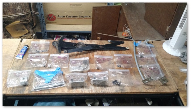
After watching the video a couple of times, I was ready to begin. I started by laying out all the hardware bits and bobbles that needed to be installed:
I then proceeded to experiment with a number of different installation steps on the passenger side window to find out what made the most sense to me. Once I was finished with the passenger side, I installed the driver’s side in exactly the steps outlined below.
NOTE: To avoid repeating myself, I’m going to omit the parts of the process where I lubricate everything I install. Just insert that step yourself mentally after everything you see below and you’ll have an accurate step-by-step accounting of what I did.
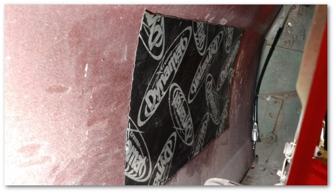
I started by installing sound deadening material:
My initial instinct was to do this last and cover the entire door, but after further research I’ve come to the understanding that would be overkill. Instead, I just cut out a reasonable section and installed it onto the outer door skin as shown above.
I then installed the window runs:
Rather unsurprisingly I immediately ran into a hiccup in that I could not figure out how they attached at the top of the door. I had a bolt and pictures showing that bolt fastening the runs to the door skin, but I couldn’t see how it was supposed to work with the mounting points I had where the runs attached:
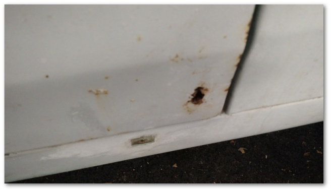
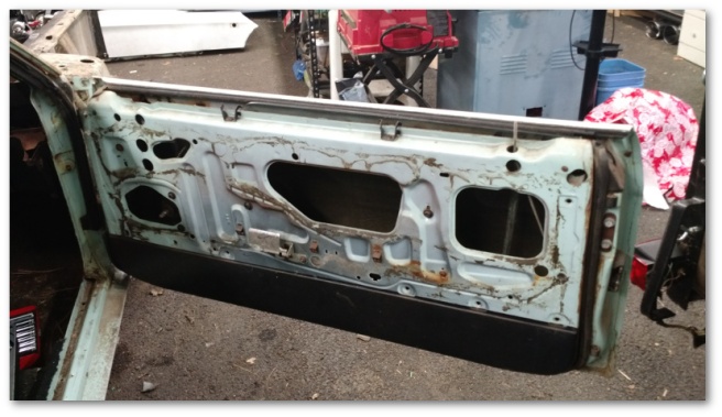
I spent upwards of 30 minutes searching on the web with little success before the solution dawned on me. If you recall, the only major rust area in the Mustang was in the doors:
The rust in both doors required me to get new door skins installed during the painting process:
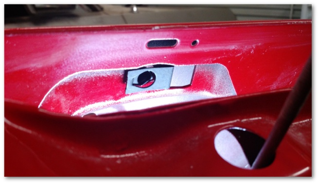
One of the unwritten rules about purchasing car parts is that you should never expect parts to come with the fasteners needed to attach them. In this case, the new door skins didn’t come with the U-Clips needed to attach the window runs. After that epiphany and a quick trip to the hardware store, the proper environment was available for the window runs to be installed:
With the window runs installed, I then proceeded to what might be a controversial step – installing the outer belt line felt:
This felt goes on the inner structure of the door skin outside of the window:
This step might be controversial because it does make installing the window itself more difficult. However, after trying to install the belt line felt with the window installed on the passenger side I came to believe that it was easier dealing with the window installation difficulties than dealing with the tiny clearances available to install the felt once the window was installed.
The next step was also learned the hard way from my experiences on the passenger side. In order for the window to install once the belt line felt is installed, you need to lubricate this \___/ shaped opening in the door frame:
As you’ll see in a minute, that opening plays a critical role in the installation of the window.
For lubrication, I used the same product I used everywhere else in the window glass installation – a product from NAPA called Sil-Glyde:
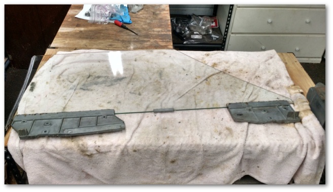
With everything ready to go on the door, I got the window out and cleaned almost two years of dust off of it:
If you’re following along at home, don’t bother to do a show-quality clean up job on the window at this time. You’ll be man-handling it during the installation process (much of the time with lubricant on your hands) and will end up gumming it all up again.
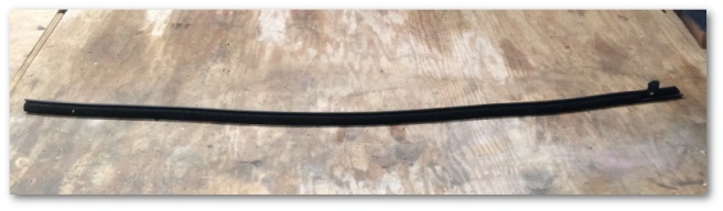
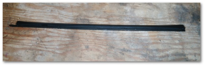
I decided to install the window weatherstripping at this time:
This weatherstrip attaches to the stainless steel channel at the back of the door window and seals the space between it and the quarter window. You may recall me procuring this strip from Craigslist almost two years ago for my passenger window. In the two years since I made my desperation Craigslist purchase, this part has been reproduced. However, the price of the reproduction part makes my Craigslist purchase seem like a bargain so I’m still glad I went that route.
With the window clean…ish and the weatherstripping installed, it was time to put it in the car. The video from West Coast Classic Cougar is great in every respect save for this part. The gentleman in the video has all sorts of problems installing the window due to the window brackets that are glued on, can’t be removed and are larger than the slot the window goes in.
As it turns out, there are a couple of alternative methods to installing the windows that work much better. The first is to install the window from the back of the door forward as shown in the following video:
I tried this technique, but quickly found that with the belt line felt installed there wasn’t nearly enough clearance to make it work. I then tried the following method described in this video:
I found that after lubricating the opening in the door frame that he slides the window brackets through I was able to fairly easily install the glass into the car.
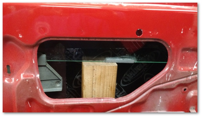
With the window installed, I needed a way to support it while I attached everything to it. For that purpose, I turned to a very specialized tool of the trade called a scrap two by four:
I was rather surprised at how well the window balanced on the wood. It balanced so well in fact that I only needed one to support the entire window in a stable fashion.
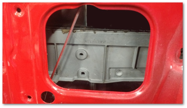
The reason I needed to support the window was to expose these bolt holes in the window brackets:
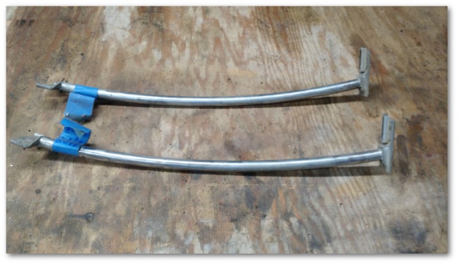
These bolt holes are used to attach the window guides:
The window guides clamp over the window run and attach to the window bracket allowing the window to stay in place while rolling up and down. The open ends of the window guides face the rear of the car.
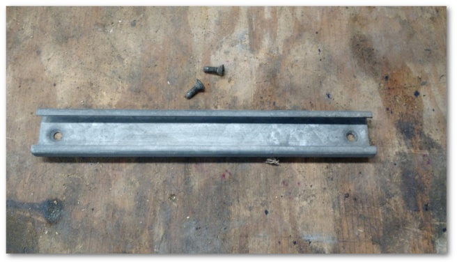
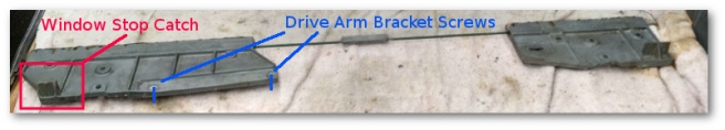
With the window guides in place, it was time to install the window drive arm bracket:
The drive arm bracket installs on the window bracket closest to the rear of the car in the following slot:
If you asked why this wasn’t installed outside of the car, you’d be asking a good question. The reason why this is installed inside the door is because the screws used to attach the drive arm bracket stick through the window bracket on the opposite side of the window stop catch:
Since these screws stick out on the opposite side of the window stop catch, they make the window bracket even wider and more difficult to install through the already tight passage in the door frame. It ends up being much easier to install these once the window is already in the door.
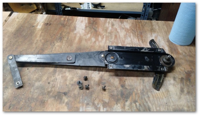
At that point, it was time to install the window regulator:
This ended up being much easier than expected. I fished the window-crank end of the regulator through the big hole to the left of the door handle and pushed it all the way forward. This allowed me to get both ends inside the door. I then slid the regulator drive arm (the arm with the plastic wheel) into the drive arm bracket:
After that, I attached the five regulator bolts to the door frame as shown below:
I found that while attaching the bolts, it was sometimes advantageous to crank the window regulator a bit. This applied a torque to the regulator and helped line up a couple of bolt holes.
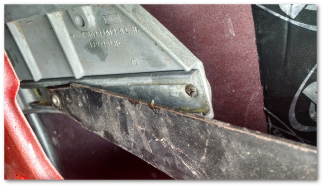
At this point, the regulator was almost fully attached. The only piece not attached was the arm that affixes to the front window bracket:
This arm attaches to the window bracket with what’s called a window bracket to regulator pivot fastener:
Note the rounded part of the nut faces out.
At this point, the window was able to roll up and down successfully. So I gave it a go and immediately found out how terribly (and unsurprisingly) aligned the window really was:
It was time to play with the window alignment to properly introduce the two glass pieces.
To begin with, I was able to grab the door window brackets and give them a heave backwards. To my satisfaction, the window moved back maybe a quarter of an inch and made a nice “thunk” sound as the window guides seated into the runs. Apparently, I had moved the window forward during my installation of the brackets and it needed a solid push backwards to get back into position.
This push back didn’t entirely solve the alignment problem though. To fully fix the issue, I needed to move the rear window forward to meet the door glass. This was fairly easy to do and the end result was rather nice for an initial fitment:
At that point, I was still rolling the window up and stopping manually at the top. The last part of the window installation was to install the window stops.
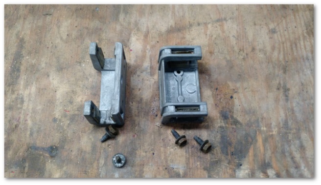
I started with the stop at the rear of the door:
The stop installs with the rubberized end pointing towards the front of the car like so:
The last window stop I installed was at the front of the door:
This stop installs with the bolt in the top slot and the slider in the bottom.
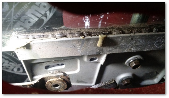
At that point, I thought I was done until I was cleaning up all the bags that had held the fasteners and ran into these little guys:
Honestly, I don’t know what they’re called or their exact purpose but after a consultation with the historical image archives it seems they install along the top of the inner door frame like this (with the flat parts facing the window and door frame) and play a role in supporting the upper door trim.
After all that, things are still not completely well in window land just yet. While the driver’s side window works great, the passenger window doesn’t roll up evenly. The back of the window starts first and seems to drag the front of the window along with it. Once the back is all the way rolled up, an uncomfortably large twist of the handle is required to finally get the front of the window to fully roll up.
I’ve swapped out everything I can with pieces from the driver’s side and haven’t been able to fix the problem. As of now, I believe the problem is a loose bushing in the window regulator. You can see that there’s a lot of slop in the video below:
The driver’s side has no such movement. I’m not a big fan of ordering parts that I’m not 100% sure I need, but in this case I felt my only option was to order a replacement window regulator in the hopes that it fixes the problem. It’ll be here sometime next week and we’ll see if that takes care of it.
The windows still need to be aligned for real, but that will require the weatherstripping to be installed first. I’m going to wait on doing that for a while until the weather warms up a bit and the rubber is a bit more malleable.
As for my next steps, I’m somewhat at a crossroads. On one hand, I would like to work on my shop to better organize my storage area. On the other hand, I don’t really *need* to do that right now and perhaps it would be a better idea to get the lower dash installed. On the other, other hand it’s still going to be cold next week and maybe staying inside by the fire will win the day.
As an engineer, I naturally like to categorize things. With the Mustang, I’ve taken to labeling tasks that take up significant amounts of time as “projects” such as Project Upholsteryand Project Electrical System. When I went to replace my door handles, I never thought that process would qualify it for “project” status, but after spending well over a month attempting to get the right parts I suppose if the classification fits I might as well use it.
I returned that package and was promptly sent door handles for a 65/66 Mustang instead of a 69. After returning those, I was sent another package with the correct 1969 part number but again containing the wrong parts.
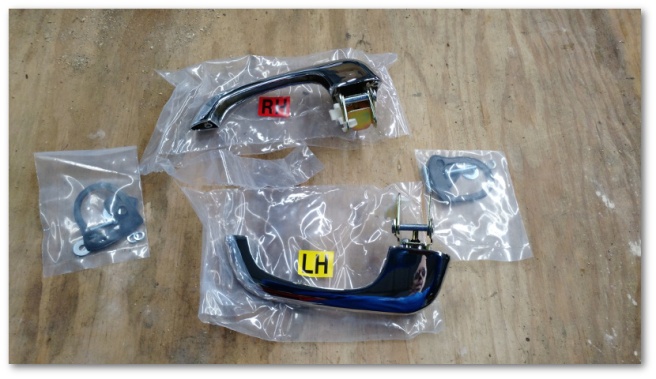
At that point, the customer service agent at CJ Pony Parts promised to “make it right” and sent me a generic brand door handle kit that was also supposed to fit 69 Mustangs at no charge:
You may recall my rather negatively opinionated nature on generic brand parts, but nevertheless I decided to give these handles their fair shake and get them installed.
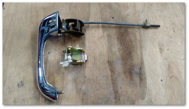
To start with, the pivots on these door handles are designed for the 65/66 Mustangs. Unlike the door handles sent to me previously though, these door handles have a mounting point for the pivot that’s compatible with 69 Mustangs. Swapping them was as simple as removing a screw and changing them out:
With the pivot attached, I was able to easily install the new door handle on to the car. They looked great!
Then I tried to use it – and promptly took it right back off.
I don’t know who made these handles, but their manufacturing tolerances leave a lot to be desired. While the door handle did function to open the door, the button on the handle was made to fit so poorly that I refused to keep it on my car:
In contrast, here’s how solid the original door handle button is:
So, after sevenshipments with four different kits from CJ Pony Parts I ended up with a free door handle kit that I refuse to use. There is one more option I could try, but after a month of dealing with door handles I was sick of it all and decided to just conclude Project Door Handles by installing my old ones and being done with it for the time being.
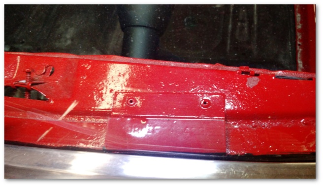
With Project Door Handles finally resolved, it was time to move on to a couple of over spray issues with my paint job:
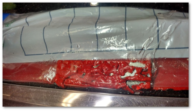
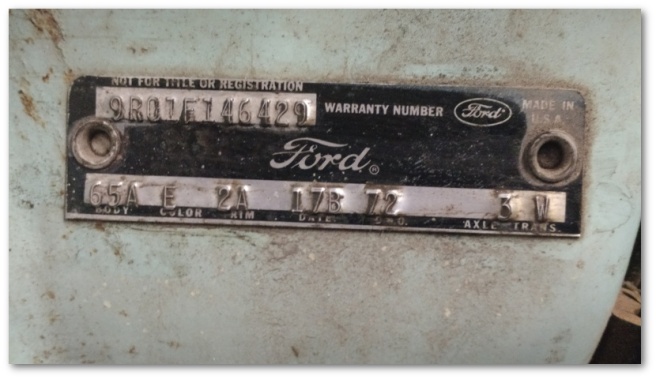
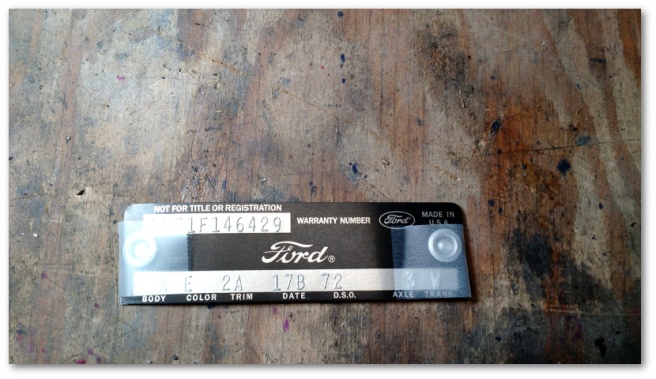
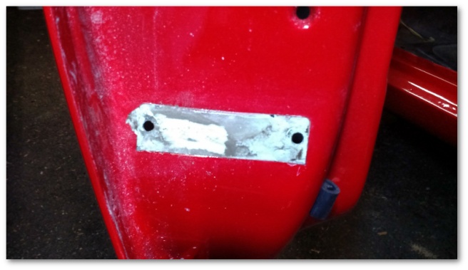
The most pressing issue was the dashboard data plate. In the condition it was in, I’m not sure I’d be able to get a DMV title ever again since the VIN was largely invisible. Being directly under the window, there wasn’t a lot of room to get in there with anything that would scrape the paint off so I had to resort to more chemically-oriented measures.
All you have to do is carefully take the old door tag off and rivet on the new one like shown in the following video:
I say “carefully” because I was in a foul mood and as a result I wasn’t careful enough and ended up chipping off some paint outside of the area where the door tag lives:
*)^*&*()&*%^$#$@#$#!!! My mood did not improve.
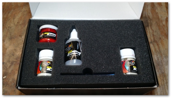
It was time to break out the touch up paint kit I purchased a while ago knowing that I would eventually foul something up and need it:
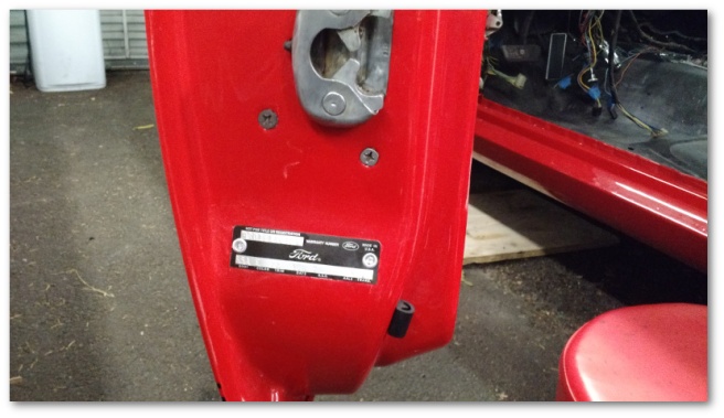
This paint kit was surprisingly good. After some sanding and a few coats of paint, I think the match is perfectly acceptable for a part of the car few will ever see without close inspection:
With the over spray issues taken care of, it was time to begin working on the windows. I’ll write an entirely separate post for that…
I am *still* waiting for correct door handles to arrive. At this point, I’ve been shipped (and returned) three door handle kits. The first and third kits were labeled with the correct part number but were very much not the correct part. The second…well…wasn’t even for my year of Mustang. The representative at CJ Pony Parts was very understanding of my frustration last week and promised to make things right. Unfortunately, making things right involves ordering a different door handle kit that’s currently back ordered…./sigh
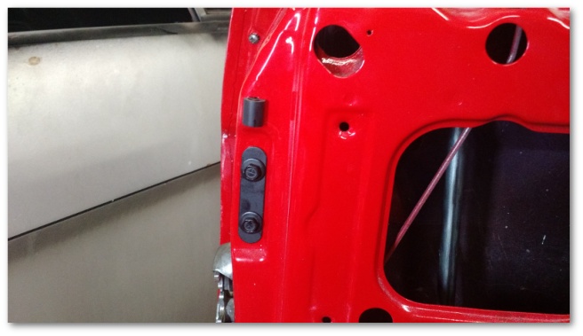
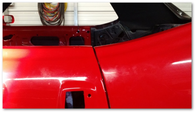
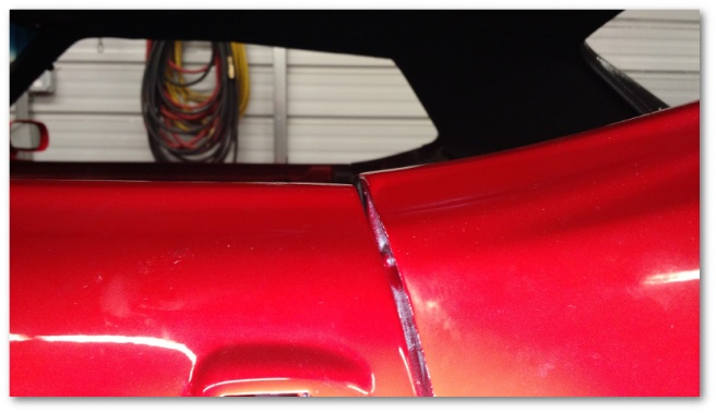
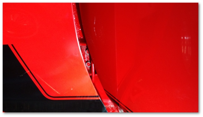
With no end to our long national nightmare of door handle problems in sight, I made some slight adjustments to the original plan for last weekend. And by “adjustments” I mean adjusting my driver’s side door:
That shot shows a fairly minor mis-alignment in my driver’s side door as it meets the quarter panel on the top. It wasn’t horrible, but it was noticeable and my OCD would have triggered every time I got in the car.
Classic Mustang doors have quite a number of adjustments possible for them. Here’s a good video describing the basics:
In the video above, you can see that the gentleman doing the presentation has full access to the bolts holding the door on due to the fact that his fender is off.
Me…well, not so much:
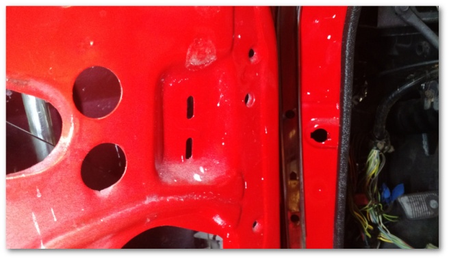
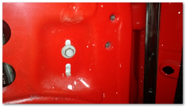
With the fender on, you can just baaaarely see two of the three bolts that hold the hinge on. With very careful placement, you might be able to get a swivel socket on those two and get them loose while at the same time risking damage to your paint.
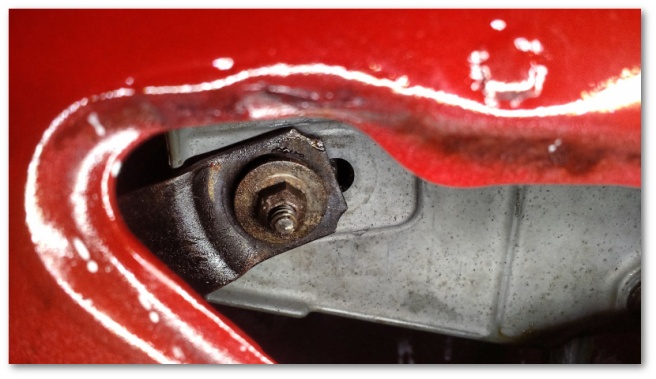
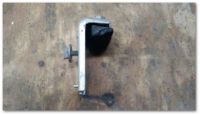
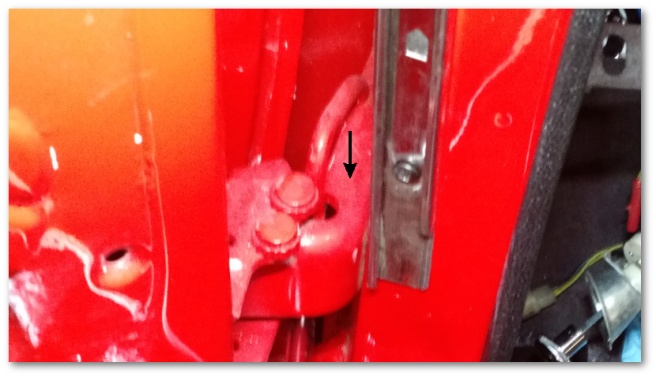
In addition to those paint-damage-risking bolts, there’s a third bolt holding the hinge on. The one you can’t see in the image above is located right about here:
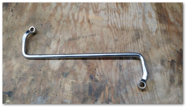
Needless to say, adjusting doors with the fenders on is rather a challenge. Unless you have the right tool for the job (tm) :
That very oddly shaped tool is a Snap-On S9608-B door hinge wrench. Like my other esoteric tools of the trade, it was built for a very specific purpose – adjusting doors of classic cars while the fenders were still attached.
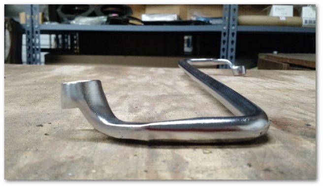
In addition to it’s weird shape, this tool also has a very deep well that allows it to seat against the door hinge bolts even though they’re buried inside the door hinge itself:
What on earth does this tool look like when it’s in use? I’m glad you asked…
You can see that the shape of the tool allows it to go *under* the hinge, loop back into the valley where the bolt lies and then dive down and seat on the bolt – all while still giving the tool holder the leverage needed to tighten or loosen the bolt. Brilliant!
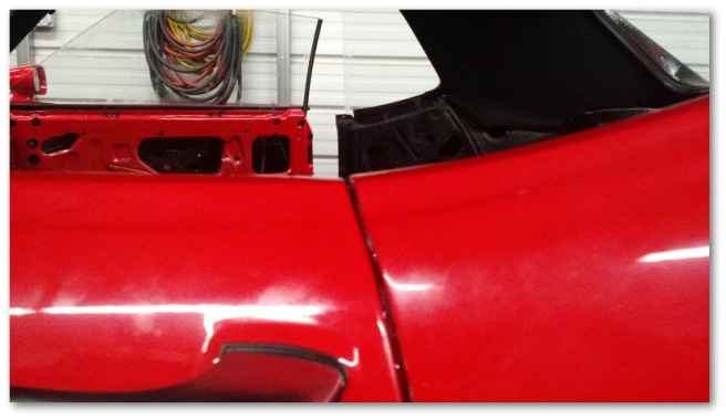
Sadly, they don’t make these wrenches any more so I had to resort to eBay to get mine. For the record, I think the fifty dollars I spent was well worth it since I was able to achieve the following in about 20 minutes of fiddling:
You’ll note that the door is now just a little high. That was done on purpose. I still need to install the window, window frame, regulator and other door goodies. Once this hardware is installed, I expect their combined weight to cause the door to drop slightly and result in a nice door/quarter alignment. If it doesn’t, well… I still have the wrench.
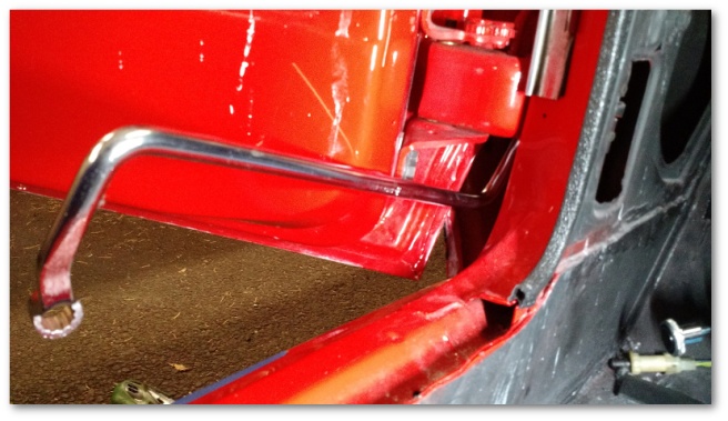
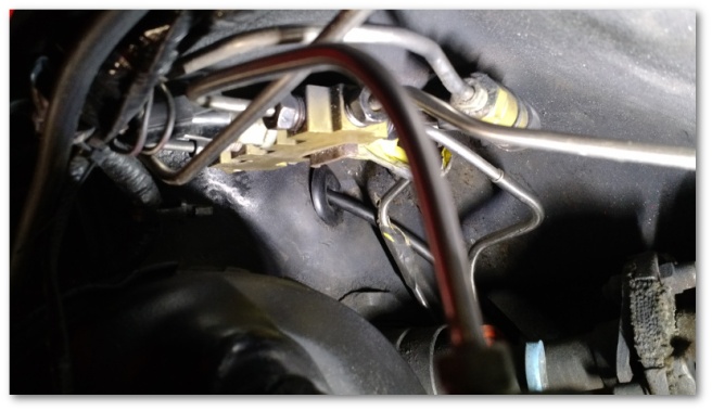
The rest of the day was spent under the car finishing up the installation of the speedometer cable and fixing the parking brake return spring.
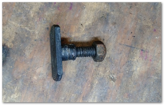
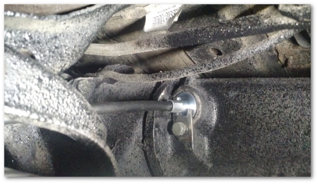
When last we left the speedometer cable, it was attached to the transmission with what I thought at the time was a broken retainer:
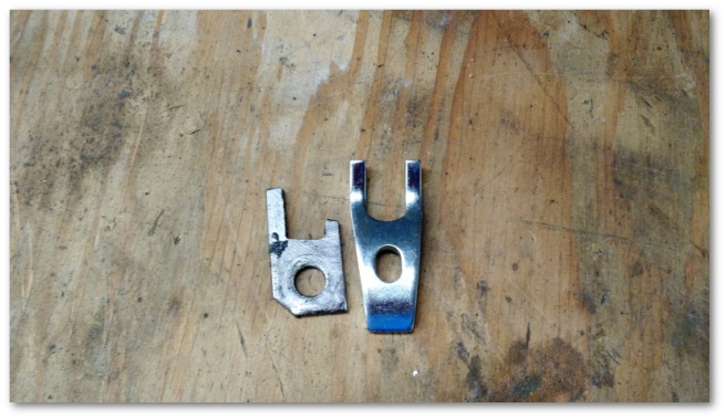
Upon receiving a new retainer and comparing it to my old one, I decided to update my opinion of the old part to “home made, broken retainer”:
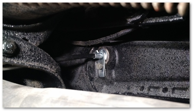
Home made or not, the old retainer is now in my excess parts bin and the new one is happily installed in its place:
With the retainer in place, I felt safe in installing the firewall grommet for the speedometer cable as well:
With the installation of that grommet, the entire front of the car from the firewall forward is done done as far as I know. WooHoo!
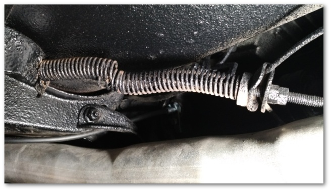
The last item I worked on was the parking brake return spring. You may recall that it was in more than a few pieces and needed a little help:
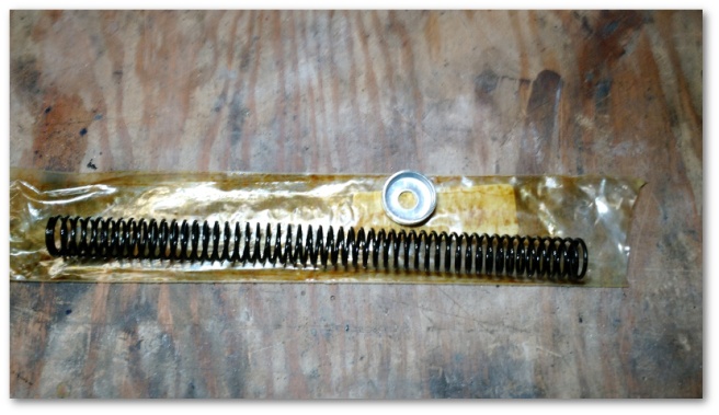
Naturally, new springs:
are only a few clicks (and 20 dollars or so) away. Installation was difficult only in the fact that the two adjusting nuts probably hadn’t moved in 50 years and I had to overcome rust and heaven knows how many layers of undercoating in order to get them off the cable.
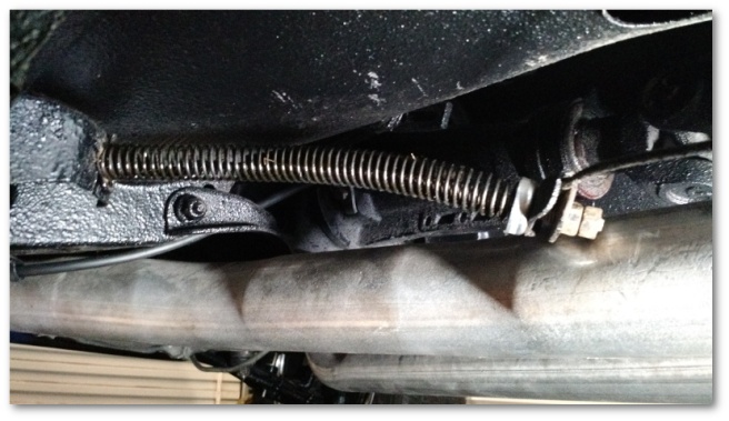
Eventually though, stubbornness won the day and the new spring was installed:
I deliberately left it un-tightened as a gift to future me when he installs the parking brake pedal assembly. Once the pedal is installed, I will adjust the cable on the bottom of the car by tightening the nuts down the same number of threads as they were originally. In theory, that should return my parking brake to working and adjusted order.
That was it for this week. Next week’s plan is to install the driver’s side door latch and lock as well as the door glass on both sides. I’m going to do this with or without new door handles as I need to get the door glass off of some shelving I’m planning on moving over my Christmas vacation as part of Shop 5.0.
It’s amazing how similar cars work in comparison to human anatomy. Humans have hearts, brains and central nervous systems. Cars in comparison have similarly purposed engines, computers and wiring. In both instances, things can sometimes go a little wrong and require a little surgery to make right:
Last weekend, my Brother-in-Law and I played the role of doctors with Mystique as our patient. Mystique’s engine/heart wasn’t working and we needed to find out why and see if we could fix it.
We also were unable to detect any evidence of spark being generated by the coil. If we would have had compression, I may have been willing to go get a new coil and/or debug further. However, with no spark and no compression time of death was called late Sunday afternoon.
One thing had been nagging me since we started my 69 Mustang for the first time after paint. During the process of getting the Mustang started, we were unable to detect any spark to her spark plugs until I realized we hadn’t attached the wiring harness that powers the coil. Without power to the coil, there can be no power to the spark plugs:
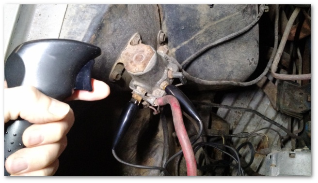
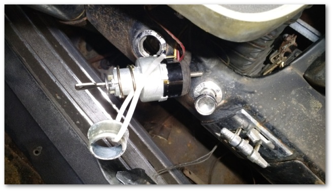
The technique my Brother-in-Law and I used last January was to hook up a switch to the starter solenoid:
When activated, this switch bypasses the keyed ignition switch and activates the starter. What I didn’t realize at the time was that while this technique provides power to the starter, it does not by itself provide power to the coil. Without power to the coil, there was no hope of Mystique ever starting.
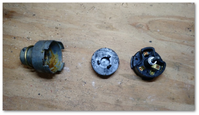
Why were we using a starter solenoid bypass switch in the first place instead of just using the key? Well, it turns out that Mystique’s ignition switch was rather spectacularly broken:
At the time, I thought it would be easier to simply use a solenoid switch than replace the ignition switch since I didn’t know the condition of Mystique’s wiring and wanted to cut out as many variables as possible. It turns out that in doing so I cut a few too many variables out. Oh well…
As it turns out, replacing an ignition switch on a 1966 Mustang is pretty easy. The switch was available at my local AutoZone for less than 15 dollars. The installation was pretty easy as well as shown in the following video:
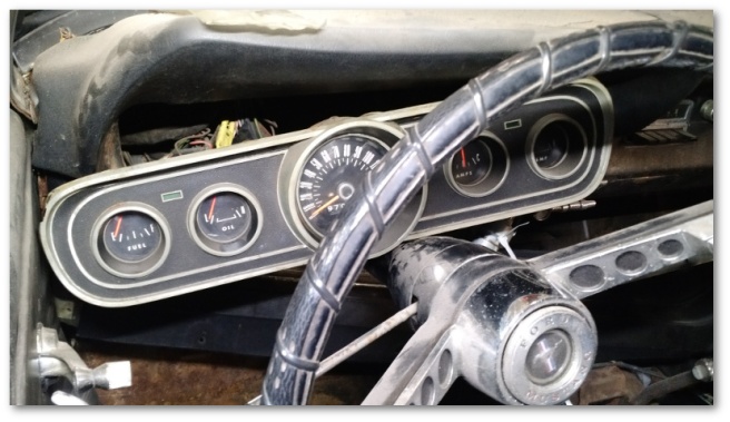
I did make one small change to the steps outlined in the video above. Rather than reach up under the dash, I decided to take the instrument cluster off. It was just a few screws and gave me much easier access to the switch:
With the instrument cluster off, I pulled the remnants of the old switch out and plugged in the new one. I didn’t completely seat the new switch since I know I’ll be removing it again in the future. Instead I just zip tied the spacer to the spring and let it hang:
With this in place, I turned the key to see what would happen. Rather to my surprise, a large portion of Mystique’s electronics responded:
As you can see, I have working (….sorta) turn signals, wipers and transmission gear indicator lights. I also had the ability to turn the engine over using the key.
Sadly, even though I could turn the engine over, we were still not detecting any spark. However, we could confirm that we were getting power to the coil so that narrowed down the problem to all of the electrical components from the coil onward.
These components were also available at my local AutoZone. We ended up purchasing a new coil, distributor cap, rotor, plug wires, condenser and set of points – essentially all the pieces required to give Mystique a tune up. After a couple of fits and starts, our surgery resulted in the detection of a heartbeat when Mystique’s engine was cranked:
Encouraged, we sprayed a little starting fluid into the carburetor just to see what would happen:
Holy Crap! That’s an engine that might actually start!
In the off chance that the engine actually did start, we pushed Mystique out of the shop to avoid killing ourselves with her exhaust and whatever else came out of her engine. We then hooked up her fuel pump to a gas can, turned the ignition switch to the ON position (which provides power to the coil), sprayed some more starter fluid into the carburetor and tried starting her again.
Have you ever noticed that sometimes when people wake up, they’re not in the best of moods? Sometimes cars have that same problem:
So yeah, Mystique got up on the wrong side of the bed and attacked my cameraman Brother-in-Law with a few projectiles thrown from her engine compartment before going back to bed.
But she got up!
For our next attempt, my Brother-in-Law decided to stand on the other side of the car (away from the direction of the radiator-fan-launched projectiles) and have me start the car using the key in the ON position (which provides power to the coil) and the solenoid switch.
At long last, our patient woke up – and stayed up:
A careful inspection of the video above will demonstrate a couple of interesting things:
Mystique did indeed start and run for an extended period of time.
It appears as though her carburetor is mal-adjusted and she runs at full throttle.
I quickly realize that I hadn’t thought through what to do if she actually did start. The dark shadow you see across the frame is me running to shut her off using the key.
My Brother-in-Law, still wounded from the previous start attempt, starts backing away from the engine on the off chance I don’t get to the key in time and it decides to explode.
Thankfully, Mystique’s engine didn’t explode. So naturally, we tried starting her again. This time without the assistance of starting fluid and using the ignition key:
Woohoo! Mystique is ALIVE! Surgery successful!
Of course, with all patients in conditions as critical as Mystique’s, additional surgeries will be required before full recovery is possible. In Mystique’s case, one such surgery will be to replace her core plugs which seem to not be able to do their job of holding in coolant:
We also discovered that Mystique has the wrong distributor. She’s a California car and is currently equipped with what’s called a Thermactor Emissions System. These systems required a different distributor than the ones used by Mustangs without the emissions system. The different distributors also require different rotors. Even though Mystique has the emissions equipment, her distributor required the non-Thermactor rotor.
Being able to start Mystique doesn’t really change any plans for her restoration. However, it’s a huge emotional hot damn inspiration that we were able to take something that had been declared dead and make it live again.
With all the activity surrounding the Mustang lately, I imagine Mystique has been feeling a little left out. Hopefully, some work I did over the weekend with my son helped a little in that regard.
A couple of weeks ago, CJ Pony Parts had a flash 50% off sale. Never one to pass up the opportunity to save some money, I clicked on the email to see what was available that I might be interested in. At the time, I thought I was done buying parts for the Mustang so I concentrated on parts that Mystique might need. I settled on purchasing a high-quality export brace.
From the factory, US-spec Mustangs had a two-piece brace set between the shock towers and the cowl:
This stock system is not well regarded and doesn’t really prevent the chassis from flexing and getting out of position over time.
Europe-bound (i.e. Mustangs for export – hence the name) were fitted with a one piece brace like the one I purchased:
This one piece brace locks the cowl and two shock towers in place and does not allow them to flex easily or get out of position. They’re a solid chassis strengthening upgrade for any Mustang (my 69 was upgraded as well) and will be especially useful if I end up turning Mystique into a convertible.
Normally, the brace that I purchased costs over 60 dollars. However, during the flash sale, it was on sale for 24. I also had a 10 dollar “loyalty coupon” that was about to expire which brought the price down to 14 – over 75% off. Shipping was free too.
I think I scored a pretty good deal.
The installation with my Son was a lot of fun. We started by unbolting the shocks, shock hats and old braces leaving the shock tower brace mounts still attached:
The shock tower braces are welded to the shock towers and aren’t easily removed. For now, I just left them in but eventually when I restore the engine bay I’ll probably cut them out to improve the aesthetics.
We were then able to set the export brace into the car and line it up on the shock tower studs. Those holes lined up easily. However, the mounting holes on the cowl needed some persuasion. Thankfully, the holes lined up well enough that I could lift the export brace up and insert a long bolt through both the export brace hole and the mounting hole in the cowl.
With the bolt through both holes, I could use my breaker bar to tighten up the nut on the bolt which had the effect of locking the export brace into the correct position and lining up the rest of the holes:
With the rest of the holes lined up, the three remaining bolts could be inserted and snugged up. Finally, the alignment bolt was removed and the last correct fastener installed. The shock hats and shocks followed quickly thereafter.
And with that, Mystique now sports a spiffy new brace in her engine bay:
This is all temporary and will be removed when the engine bay is restored. For the time being though, it was nice to work on Mystique with my son and get a simple project completed.
Speaking of Mystique, I recently discovered that the technique my Brother-in-Law and I used to try to get her engine started didn’t provide power to the coil. This means that there was no chance that the engine would have started with what we were doing.
Just for kicks, we’re going to try to get her started again in the near future using a different technique. Considering the very low compression in the engine, I don’t expect much even if we do get her started. Nevertheless, it’ll be neat to give starting her another shot and see if we can get further.


-1028.jpg)