
I took advantage of a long holiday weekend to knock a bunch of stuff off the electrical TODO list.
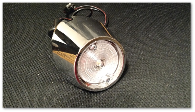
First on the docket was the installation of the LED reverse lights which finally arrived a week or so ago. These lights come on a little circuit board with an adapter that plugs right into the old light socket in the reverse light assembly:

Once they’re assembled with the lens, they look almost stock but with a slight “something is different” flair:
That flair becomes readily apparent when the reverse lights are turned on and you see how much brighter the LEDs are to the standard incandescents:

My eye doctor told me not too long ago that as I age, my eyesight will steadily degrade. Having the extra light when backing up will allow me to pretend he doesn’t know what he’s talking about for perhaps a couple more years.
After I took that shot, I replaced the reverse light assembly on the right and now have two LED searchlights available for my rear illumination needs.
I also replaced the incandescent bulbs in the tail light assemblies with a solid state sealed LED unit. The tail light assemblies come apart easily:
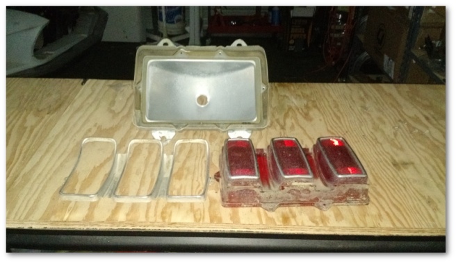
All I had to do was replace the original red lens with the sealed LED unit:


These lights are plug-and-play just like the reverse lights in that they hook right into the same light socket that the old incandescent bulb plugs into. This design means I don’t have to mess with my wiring at all and I can always go back to stock if I ever wanted to.
After I installed the LEDs on the left, I did another comparison between the performance of the LEDs and the stock incandescents:
You can see that the LED on the left illuminates much more quickly than the incandescent on the right. While this is a really cool visual, it also has some important safety implications.
Take a look at a frame-by-frame analysis of the video above:
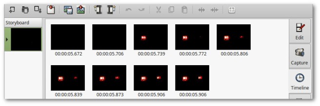
Here’s the sequence of events that can be seen in the recording:
- At 5.706 seconds both lights are off
- At 5.739 seconds, the LED is fully illuminated but the incandescent is still dark
- At 5.806 seconds, the incandescent begins to illuminate
- At 5.906 seconds, the incandescent is fully illuminated
Doing the math, this means the person behind me sees my brake lights 167 milliseconds faster with LED’s than with incandescents. While that might not sound like a lot, at 60 miles per hour a car is traveling at 88 feet per second. 167 milliseconds of extra warning time basically means I’m giving that driver behind me an extra 14.5 feet of stopping space – longer than the length of the Mustang.
I also like that the hazards actually flash, rather than fade in and out:
The only small hiccup in the LED plans for the day was the emergency flasher relay. The LED relays I purchased have to be wired a specific way with +12v applied to a particular pin. The turn signal wiring is wired the way the relays need to be, but the hazard lights are backwards.
I was initially fairly annoyed at this, until I realized the upside to the situation. I ended up going to Amazon.com and purchasing a harness that will plug into the Mustang’s existing hazard relay junction. This harness has two wires coming out of it that will allow me to then plug in the relay in a way that will make it happy. The really nice part is that this design also lets me hook into the new harness to power the radio and electric choke without modifying the Mustang’s original wiring. I’ll take a day or two of delay for that benefit every time.
The next major TODO item knocked off the list (kinda sorta) was the rebuild of the instrument cluster. I’d been avoiding this because I figured it would be a pain. Nevertheless, it needed to be done so I started with my brand new cluster bezel:
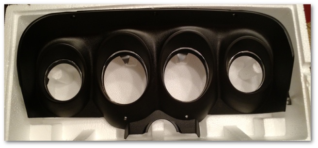
Attached to that bezel were brand new lenses and a brand new printed circuit board. While the previous sentence took maybe 10 seconds to write, getting all these new pieces attached to each other along with the parts I cleaned up last weekend took well over an hour.
Finally, though I got it all assembled:
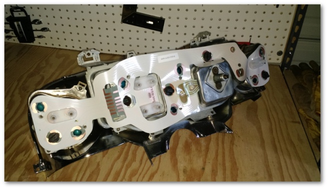
Then came the hard part. All those little holes you see in the instrument cluster needed to be filled with LED bulbs:
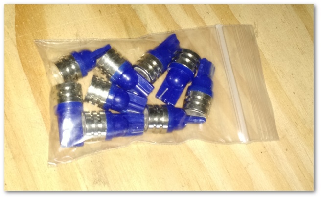
The problem with these cute little bulbs is that they can only be inserted in one way. If you get them in backwards, they don’t light up. I thought about pulling in an external power supply and pre-wiring the bulbs up, but naturally that thought didn’t occur to me until after I’d attached the instrument cluster to the dash wiring and spent about 45 minutes blindly fiddling with lights.
In the end though, it was worth it:

The old color of the instrument cluster was a greenish hue. The new LEDs turn that into a brilliant blue color that I really like. The red horse you see is the high-beam indicator – which I also think is really cool.
Sadly though, today was not without its setbacks.
The gauges don’t work. Including the oil pressure gauge that previously did.
After I installed the cluster, I tested both the gas and temp gauges by turning the ignition switch to the ON position and grounding the leads that connect to the fuel and temperature sending units. Both gauges responded as they should have which I took as a really good sign. However, while I was doing the tests, I noticed that the pulse of power that I should be receiving from the instrument cluster was in fact a steady stream of power. I logged this in the “thinks that make your go hmmmm” category and proceeded with starting the car. I hoped to see the temp and oil pressure gauges move over time. I didn’t expect much out of the gas gauge because there’s not that much gas in the tank.
It was not to be sadly. There wasn’t so much as a wiggle from either of the three gauges.
The constant stream of power gave me a decent clue though as to where to start debugging. All three of the non-working gauges are driven by what’s called a constant voltage regulator. This regulator is attached to the instrument cluster and is supposed to send pulses of power to the sensors that read the oil pressure, temperature and fuel level. Since all three of those gauges aren’t working and because I wasn’t seeing the pulses I expected I’m going to start looking there.
I’m a little bummed by this. I purchased a new regulator so it should have worked. I don’t think I installed it wrong, but we’ll find out soon enough. I’ve pulled the cluster off for now and will do some bench testing this week to see if I can find the problem.

2 thoughts on “LED Happiness, Gauge Setbacks…”