
Today was a day of tying up loose ends – specifically the loose ends of the gas and temperature gauge wiring. The gas gauge wiring just needed to be re-connected with the grommet and pig-tail connector I fixed after my road trip from last week.
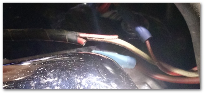
The temperature gauge wiring has been loose and unconnected to anything ever since I brought the Mustang home. In fact, it looks as though it was deliberately cut at some point in the past:
I started by building a high tech, state-of-the-art soldering jig to hold wires in place while I was soldering them:
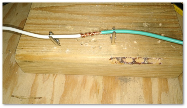
I then cut out a length of extra wire from the salvage yard wiring grommet and soldered it and the wiring grommet into the trunk’s wiring harness:

I added the extra bit of wiring to give me a little more slack than what I had before. This gives me enough wire to hide the wiring in the rear quarter panel’s wheel well much easier in the future.
Before moving on, I wanted to test the entire circuit end to end in order to make sure the instrument cluster had a clear connection for the gauge. Once again, I turned to a high-tech solution involving:
Alligator clips: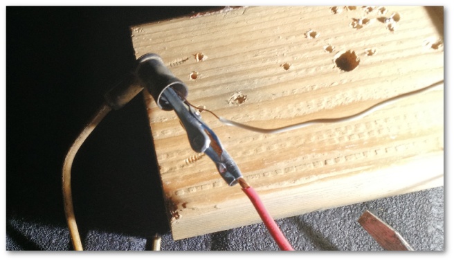
Connected to a long length of wire:
Connected to my multi-meter hanging from the dash:
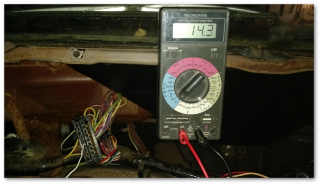
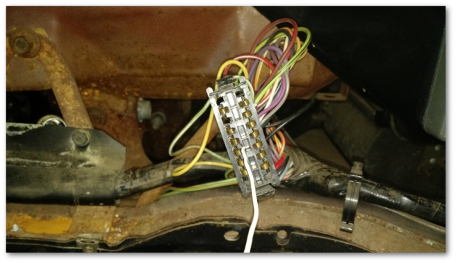
Which was then connected to the instrument cluster harness’ (thanks again wiring diagram!) gas gauge slot.
After all that, I heard the satisfying “beeeeeeeeeeeeep” of my multi-meter telling me there was a clear connection. I then plugged the unit into the sending unit under the car.
One loose end tied up.
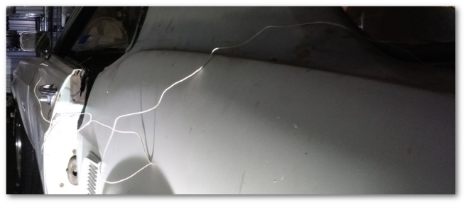
The next loose end was the temperature gauge wiring. It was a mess. The previous owner had attempted to wire a stand-alone gauge into the dash with a hodgepodge of wires. I have to assume he did this because the gauge in the dash wasn’t working – but the way he wired it was ridiculous:
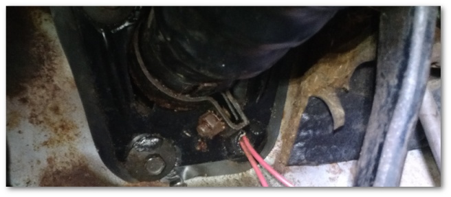
Yup, that’s the wire that he ran – straight through a removed steering column bolt hole. It gave me great pleasure to rip that out.
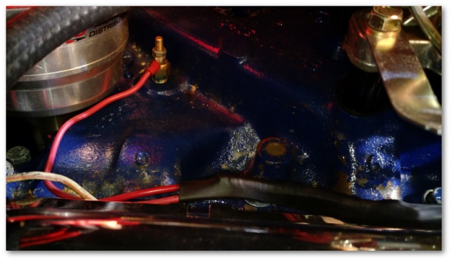
Once I was finished with the Mr. Previous Owner’s extra-curricular wiring removal, I turned the attention of my state-of-the-art gauge circuit tester towards the front of the car. Once again, the wiring diagram proved it was worth its weight in gold. Using the wiring diagram, I was able to locate the short stub of wire in the back of the engine bay that was supposed to connect to the temperature sensor:
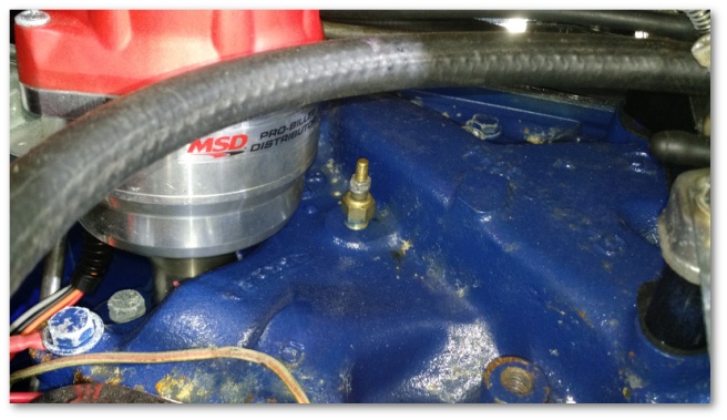
This wire was quickly soldered to a new one of the proper length to reach the sensor.
Another loose end tied up.
I then decided that three long, independent wires (temp sensor, oil pressure sensor and coil) running under my carburetor’s throttle assembly was probably not a good idea. I resolved the problem by adding three lengths of shrink wrap around all of the wires to make a single unit that was much better behaved:
Another loose end I tied up today was the rear side-marker LEDs. I had replaced the incandescents last weekend with white LEDs, but I wasn’t totally happy with the result. The bulbs were bright enough that the color was a little washed out – making the running lights look “less red” than I wanted.
I solved that problem by purchasing some red LED’s of the same type I used in the forward (amber) running lights:

When plugged in, these lights produced a brilliant deep red that I was delighted with.
The last loose end I took care of today was investigating the short in the driver’s side rear tail light. As it turned out, there was no short at all. The problem was that the light grounds through the tail light assembly and the assembly didn’t have a good ground connection. Once I sanded off a little of the undercoat to expose bare metal, the light behaved exactly as it should – even after I enthusiastically fiddled with it for a few minutes.
After today’s work, here’s the current TODO list for the electrical system:
Not tested yet:
- Radio (I suppose I need to get one, I don’t really listen to the radio that much but I also don’t want a big hole in my dash)
- Climate control lights
To Do:
- Rebuild the instrument cluster
- Wire up the electric choke (parts on order)
- Clean all connectors on fuse box (on hold until I take the lower dash off)
- Install the spiffy new LED brake lights that are on order
- Install the spiffy new LED reverse lights that are on order
- Install the new flasher relays that are on order. These new relays are required due to the fact that the new LED brake lights draw so little power that the old relays (which rely on heat from all the current flowing through the incandescent bulbs) won’t work
- Install the new front turn signal assemblies that I just ordered
- Install the steering wheel
I took the “non functional” gas and temperature gauges off the list since I now know the wiring to the instrument cluster is fine. I’ll take a look at the gauges themselves when I rebuild the instrument cluster.
I also did one more thing this week that I can’t tell you about just yet. Stay tuned later in the week for details :)

One thought on “Soldering On…”