What I Plan And What Takes Place Ain’t Ever Exactly Been Similar…

In 2005, the movie Serenity was released to theaters. It was written and directed by Joss Whedon (of recent Marvel Avengers fame) and was the continuation of the cancelled-far-too-soon TV series Firefly.

Serenity was an awesome movie, and contains one of my favorite lines of theatrical dialog ever. It just so happens that this dialog also describes perfectly how today’s day went:


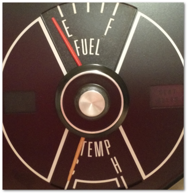
So, where to start? Let’s go back to last Sunday when I discovered my gas, temperature and oil pressure gauges weren’t working.

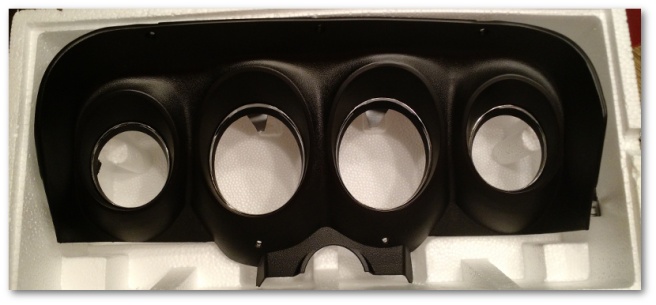
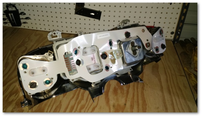
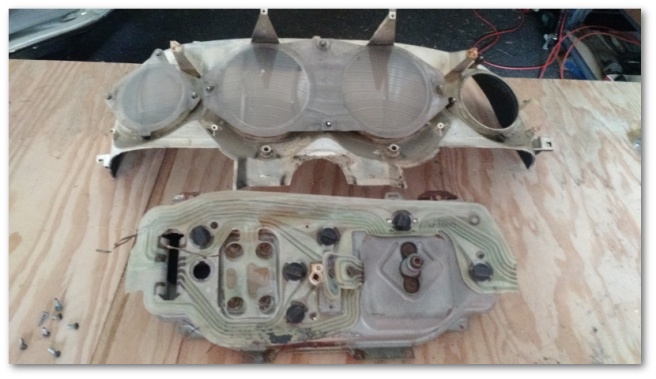
That night, I took the instrument cluster totally apart. I figured if there was something wrong with it and if I had to take it apart I might as well take advantage of the opportunity to make a few things better.

Last week, after I installed the salvage yard gas gauge I discovered that the needle had a slightly different color orange than my original temperature gauge’s needle:

different color gauges

My first attempt to make this better was to simply use the temperature gage from the salvage yard instrument cluster as well. This gave me consistently colored needles, but when you took a close look, neither salvage-yard gauge face was in the best of shape.


I tried cleaning the face plates, but the problem wasn’t dirt or grime. The surface was pitted and starting to corrode so there wasn’t much I could really do. Unfortunately, these gauges are 70 dollars each. I really didn’t want to spend that if I didn’t have to – especially since it appeared as though both gauges were functional.

So I did what any self-respecting engineer would do when presented with a similar problem.
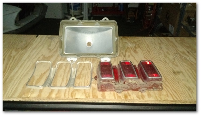
I took them apart:


In the end, I used the face plates from my Mustang with the actual gauge guts from the salvage yard instrument cluster. From what I’ve read, the gauge guts are all interchangeable between oil, temperature and fuel so I could have used any of the gauges in any place. However, as it turned out I used the salvage yard gauges for their original jobs. In the end, I had the best of all worlds – nice gauge faces and consistently colored needles.

I also took the opportunity to fix a light-leaking problem around the oil pressure gauge:

light leaking from oil pressure gauge

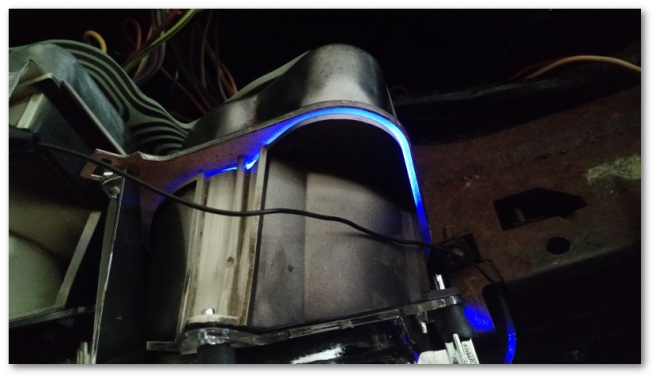
When I put the instrument cluster together, I must have let the gauge slip internally and it ended up not quite aligning with the cluster and leaking light out. It wasn’t a big deal but again since I had the cluster apart it was worth fixing.

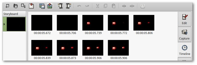
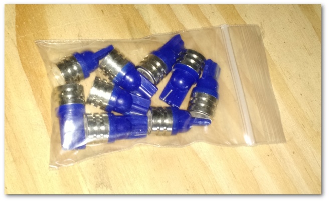
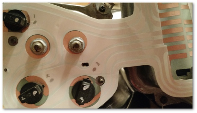
Putting the lights on the instrument cluster was much easier this time thanks to a great suggestion by my lovely wife. After listening to me grouse about having to use trial and error to get the lights installed right, she made the brilliant suggestion to label each bulb and put an indicator on the bulb housing and circuit board that would indicate how the bulb should be installed:

bulbs labeled for installation

With this set up, the lights no longer presented a problem during installation. After I got the instrument cluster all put back together, I bench tested it.

And the gauges still didn’t work.

After a few minutes of pouting and a minor temper-tantrum, I got to work figuring out why. The gauges themselves worked individually when I tested them, so why didn’t they work when they were installed inside the instrument cluster?

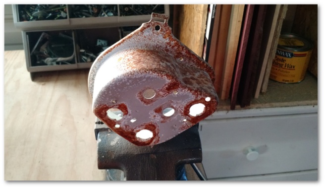
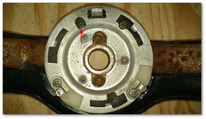
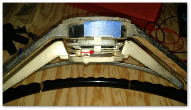
As it turns out, it was this little guy’s fault:

gauge insulator

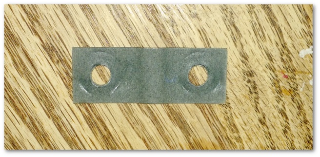
That’s the insulator for the fuel gauge that was installed between the metal instrument cluster housing and the circuit board. This insulator serves two purposes:

  1. To make sure that the circuit board isn’t grounded by the fasteners attaching to the gauge
  2. To keep the metal gauge posts centered and not grounded to the instrument cluster housing

The insulator above failed job #2 and grounded the fuel gauge. In doing so, it also grounded all of the other gauges – which was a nice little trick.

So, after taking the cluster apart for the third time and fixing this little problem I bench tested it again. Finally, all of the gauges pegged when I touched their output post to ground and all of the lights lit up when I applied power at the appropriate terminal.

The instrument cluster was tested and as ready as it was going to get.

Which brings us to today and things not going as planned. The &*(^$^&*&^ gauges still didn’t work. I took a long walk.

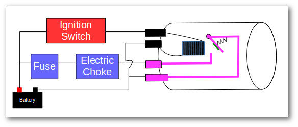
To describe how I debugged the problem, I first need to explain how these gauges work.

In 1956, Ford started using 12 volt electrical systems instead of the 6 volt systems they had historically used. However, their car’s gauges still used 6 volts – presumably because they had millions of gauges lying around and didn’t want them to go to waste. To get the correct voltage for the gauges, a “constant voltage regulator” was designed that would step down the voltage from 12 volts to 6 volts.

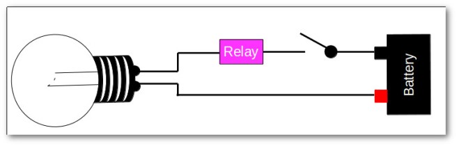
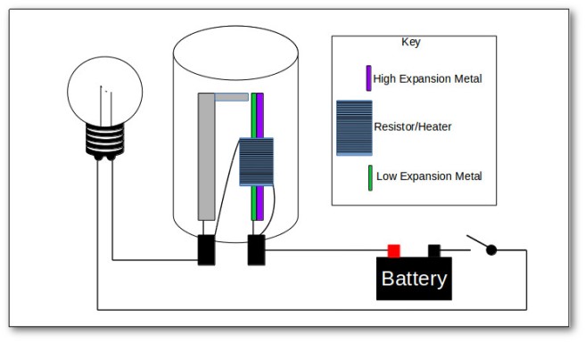
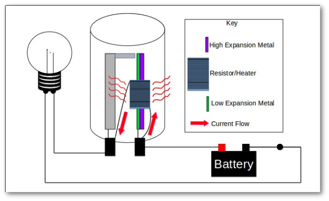
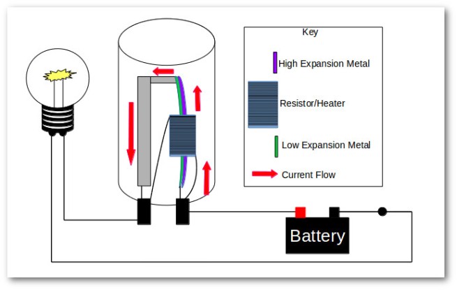
In 1969, this constant voltage regulator worked very much like the thermal relays I described in a previous post. It would oscillate between 0 and 12 volts as the relay inside it actuated and connected/broke the circuit. This oscillation would “average out” to 6 volts and make the gauges happy.

During my debugging, I discovered that today’s constant voltage regulators are solid state and provide a steady voltage that does not oscillate. This constant voltage is then applied directly to the gauge which is wired in series with a sending unit.

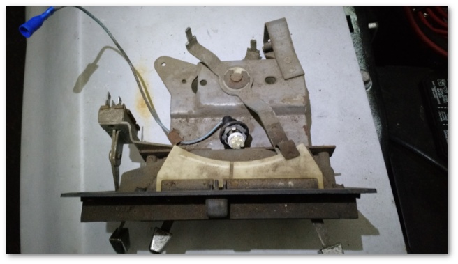
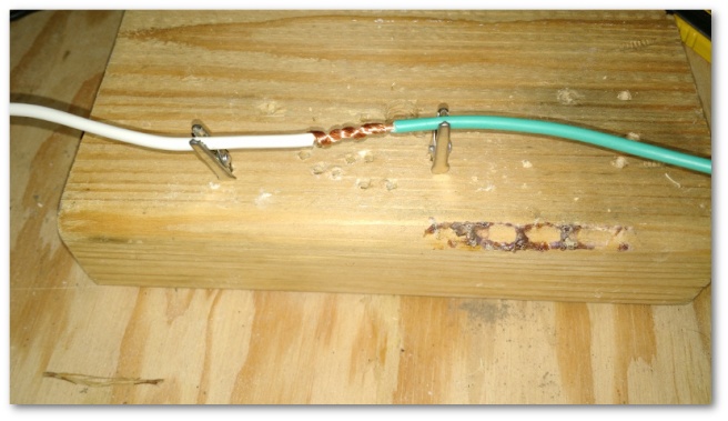
The sending unit is essentially a resistor that varies in resistive strength depending on some input or another. In the case of the fuel sending unit, it varies depending on how high the float is:


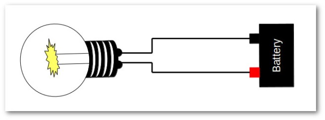
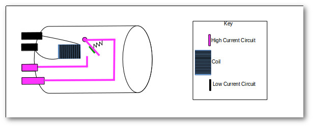
The circuit essentially looks like this:

gauges with sending units on high resistance

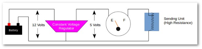
When the sending unit is in the high-resistance state, very little current flows through the gauge and it reads empty or low.

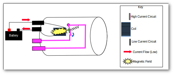
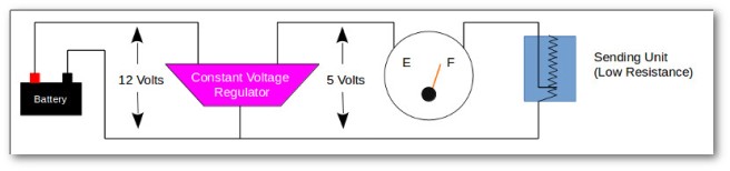
When the sending unit is in the low-resistance state, more current flows through the gauge and it reads higher and higher:

gauges with sending units on low resistance

From what I’ve been able to find during my research, the sending unit resistance specification is the following:

78 Ohms – Low peg
65 Ohms – Empty, Low or Cold
39 Ohms – 1/4 scale
24 Ohms – 1/2 scale
15 Ohms – 3/4 scale
10 Ohms – Full, High or Hot
0 Ohms – Top peg

With this knowledge, I set out to debug why the bloody gauges weren’t working.

The first thing I did was to ground both the temperature and oil pressure gauges. This should have (and did) peg both gauges at high. This told me (again) that the wiring from the instrument cluster to the sending units was just fine.

After re-attaching the oil pressure sending unit wire, it decided to start working just fine. Huzzah! One easy fix done just by re-seating a connector.

Unfortunately, the temperature gauge refused to move – even after running the car to its normal operating temperature. At this point, I decided I needed something that would simulate the proper resistance settings for my sending units.

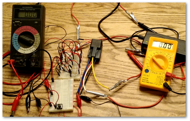
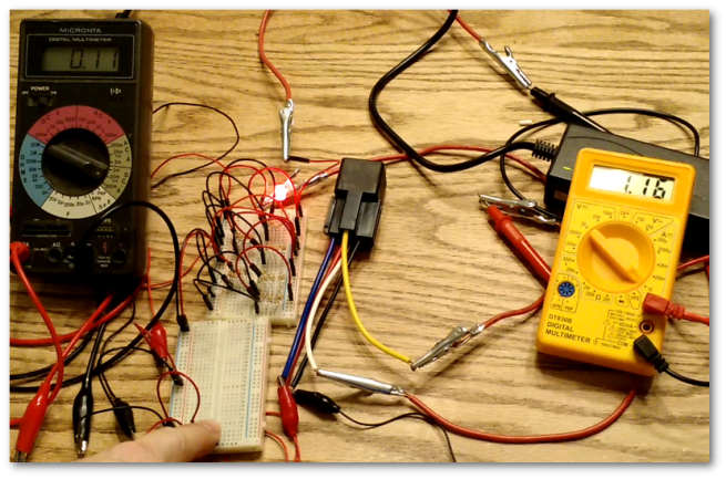
I hadn’t been to a Radio Shack in almost a decade. When I was in college I went there all the time to pick up electrical components for my classes. I decided to give them a try to see if I could find some resistors that would allow me to simulate a sending unit providing data.

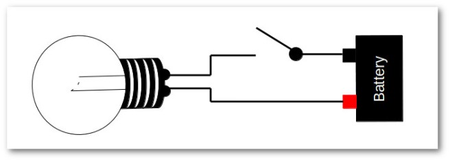
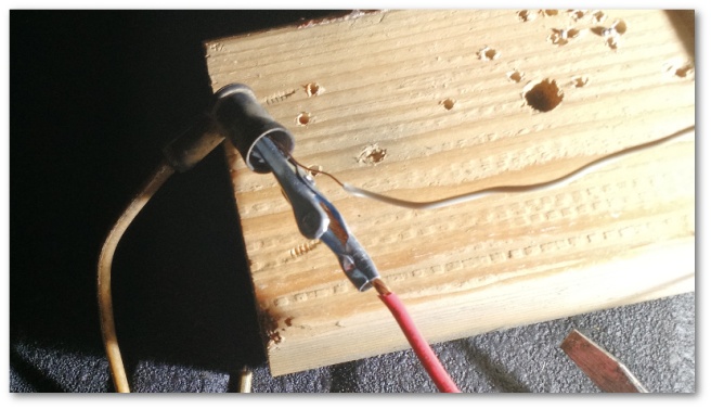
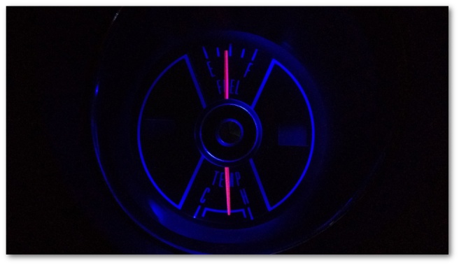
I didn’t find exactly what I wanted, but what I did find was enough to wire up my gas and temperature gauges like this:

gauge circuit with resistors instead of sending unit

With that circuit, I expected both gauges to read roughly at their mid-point. And sure enough, they did:

gauges reading half

And thus began today’s nightmare with sending units.

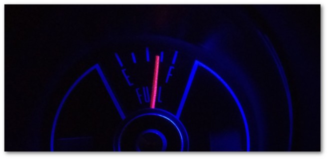
To start with, I measured the resistance at the terminal of the fuel sending unit. This gave me 80 Ohms – a reading that made sense because I knew there wasn’t much gas in the tank. Filling the tank up though only gave me a reading of 16 Ohms. I have no idea why the sending unit is misbehaving like this. In the video above you can see the unit read 12 Ohms when the float was all the way up. But, for whatever reason today it decided full was equal to 16 Ohms. This meant that the gauge should have read roughly 3/4 of a tank in this state.

And sure enough:

gas gauge reading three quarter full

So… crap.

Right now, the gas tank is full of very expensive non-ethanol gas that I don’t want to waste by draining the tank to replace the sending unit. I will fix this eventually, but for right now I’m going to move on and loop back later to fix it.

So, two gauges down – sorta.

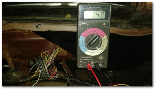
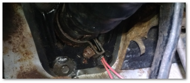
The temperature sending unit proved to be a huge pain in the ass. With the car at running temperature (189 degrees Fahrenheit according to my infra-red thermometer) the sending unit was stuck at 201 Ohms:

bad temp sensor

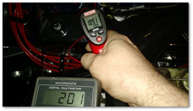
Considering the gauges expect at most 80 Ohms it’s no wonder why the temperature gauge would never budge.

After spending the better part of the day debugging this stuff, I was pretty much done with trying to debug this any further so I went down to the parts store and asked for a temperature sending unit for a 1969 Mustang. They had one in stock with the right resistance specifications and I went home with a plan to quickly swap out the part and be done for the day.

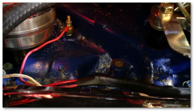
In order to install the sending unit, you have to drain the radiator out a bit so that the level of the water is below the hole in the intake manifold the sending unit is installed into. I did this and then took the part out of the box to install.

THE SENDING UNIT DIDN’T FIT INTO THE INTAKE MANIFOLD!!!

It didn’t even come close. The threading for the sending unit was way to large to fit into the itty-bitty little hole I had on my intake manifold. Aghast, I pulled out my original intake manifold to see if I had a sending unit still attached there that I could use. I didn’t (naturally) but pulling the original manifold out served to deepen the mystery even further. The new sending unit fit into my original intake manifold just fine.

Back to the parts store I went.

Me: “This sending unit doesn’t fit. Is there another type for a 69 Mustang?”

Parts Guy: “Uh no. That’s the only one, and it’s the right one for your car”

Me: “You sure?”

Parts Guy (rolling eyes): “Pretty sure, yeah”

So… Crap

At this point, I was out of ideas. It was obvious that the temperature sending unit I had on the car wasn’t giving the gauges the data they needed to display properly. However, I couldn’t replace the sending unit because the new one provided by Mr. Eye-Rolling-Pretty-Sure-That’s-The-Right-Part Guy didn’t fit.

I was about ready to call it a day until I realized something. As it turns out, I don’t actually know that my intake manifold came from a 1969 Mustang.

When we rebuilt the engine, we decided to replace the stock 2 barrel intake manifold with

a 4 barrel intake manifold that was sitting on the ground next to the car and was thrown in when I purchased it.

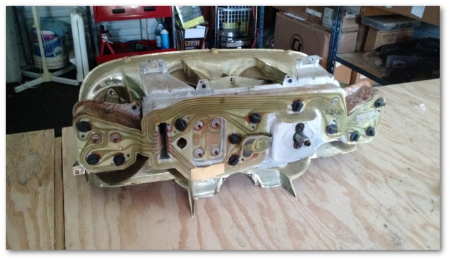
Ford made the 302 engine for forty-some-odd years. I needed to find out what year and what model so I could get the correct temperature sending unit for it. Easy, right?

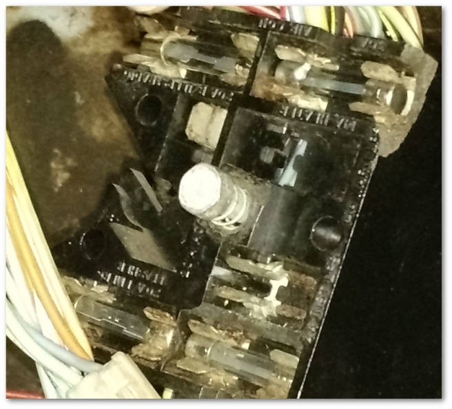
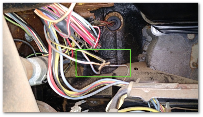
Actually, much to my surprise – yes:

inake manifold stamping

The image above shows the casting part number for my intake manifold. Ford casts these numbers onto many of the parts in their cars to help identify the parts – which was exactly what I needed to do.

A brief google search led me to a site where you can decode these casting numbers. According to that site, here’s the resulting decode of the number above:

C: Car made in the 1960’s
4: Car made in 1964
O: Ford Fairlane
E: Engine Component

So, my intake manifold is from a 1964 Ford Fairlane. Today I learned.

Doing even more research, I learned that around 1966, Ford changed their intake manifolds to have different receptacles for their temperature sending units. This was very promising!

The Napa I normally use was closed, but my neighborhood AutoZone was still open so back to the parts store I went:

Parts Guy: “Hi! What are we working on today?”

Me: “Uh.. umm… A 1964 Ford Fairlane?”

Parts Guy: “What do you need for it?”

Me: “A temperature sending unit”

Parts Guy: “Got one in stock. 11 bucks”

Me: “Sold”

The parts guy didn’t have access to the specification for the sending unit’s resistance so I brought the part home not knowing if it would actually work. The first thing I did was shove the unit into a pot of almost-boiling water to see what it would read at the Mustang’s normal operating temperature.

38 Ohms! Very, very promising!!!

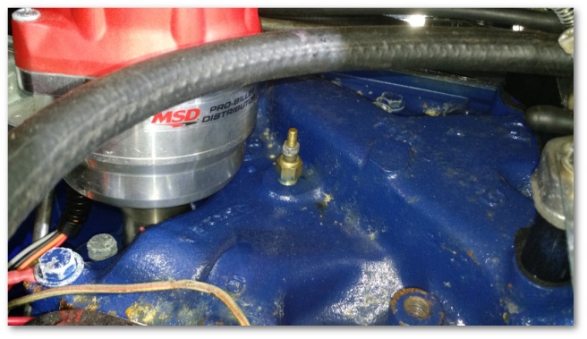
I then went down, drained the radiator again and installed the new, new temperature sending unit.

And finally, my long nightmare of a day with sending units came to an end:

all three gauges working

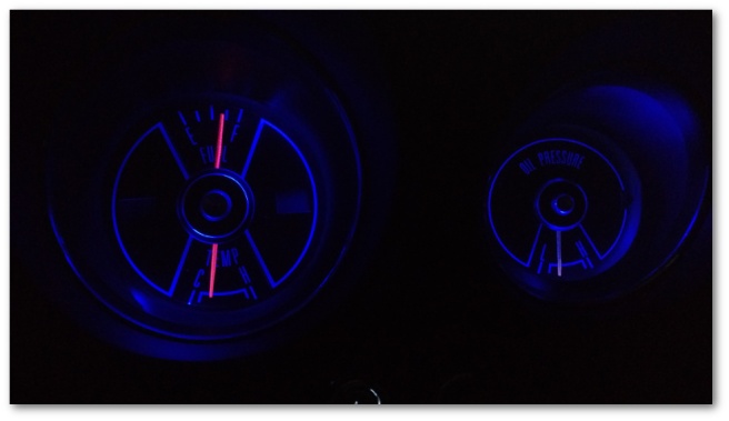
At this point, I’m declaring gauge victory. I will eventually replace the fuel sending unit, but that can be done any time.

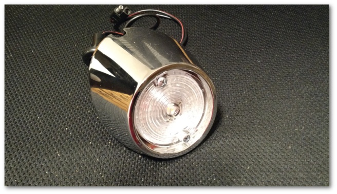
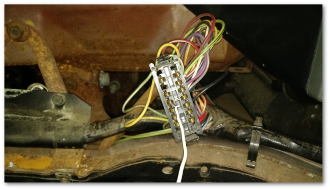
For what it’s worth, I also got the emergency flashers working today using the new wiring harness that allows me to reverse the polarity of the original socket.

Today’s original plan was to hook into this harness and wire up the choke and the radio. However, what I plan and what takes place…

You know the rest.

LED Happiness, Gauge Setbacks…

I took advantage of a long holiday weekend to knock a bunch of stuff off the electrical TODO list.

First on the docket was the installation of the LED reverse lights which finally arrived a week or so ago. These lights come on a little circuit board with an adapter that plugs right into the old light socket in the reverse light assembly:

led reverse light components

Once they’re assembled with the lens, they look almost stock but with a slight “something is different” flair:

led reverse light assembled

That flair becomes readily apparent when the reverse lights are turned on and you see how much brighter the LEDs are to the standard incandescents:

led vs standard reverse light

My eye doctor told me not too long ago that as I age, my eyesight will steadily degrade. Having the extra light when backing up will allow me to pretend he doesn’t know what he’s talking about for perhaps a couple more years.

After I took that shot, I replaced the reverse light assembly on the right and now have two LED searchlights available for my rear illumination needs.

I also replaced the incandescent bulbs in the tail light assemblies with a solid state sealed LED unit. The tail light assemblies come apart easily:

tail light assembly taken apart.jpg

All I had to do was replace the original red lens with the sealed LED unit:

These lights are plug-and-play just like the reverse lights in that they hook right into the same light socket that the old incandescent bulb plugs into. This design means I don’t have to mess with my wiring at all and I can always go back to stock if I ever wanted to.

After I installed the LEDs on the left, I did another comparison between the performance of the LEDs and the stock incandescents:


You can see that the LED on the left illuminates much more quickly than the incandescent on the right. While this is a really cool visual, it also has some important safety implications.

Take a look at a frame-by-frame analysis of the video above:

led vs standard bulb frame by frame

Here’s the sequence of events that can be seen in the recording:

  • At 5.706 seconds both lights are off
  • At 5.739 seconds, the LED is fully illuminated but the incandescent is still dark
  • At 5.806 seconds, the incandescent begins to illuminate
  • At 5.906 seconds, the incandescent is fully illuminated

Doing the math, this means the person behind me sees my brake lights 167 milliseconds faster with LED’s than with incandescents. While that might not sound like a lot, at 60 miles per hour a car is traveling at 88 feet per second. 167 milliseconds of extra warning time basically means I’m giving that driver behind me an extra 14.5 feet of stopping space – longer than the length of the Mustang.

I also like that the hazards actually flash, rather than fade in and out:


The only small hiccup in the LED plans for the day was the emergency flasher relay. The LED relays I purchased have to be wired a specific way with +12v applied to a particular pin. The turn signal wiring is wired the way the relays need to be, but the hazard lights are backwards.

I was initially fairly annoyed at this, until I realized the upside to the situation. I ended up going to Amazon.com and purchasing a harness that will plug into the Mustang’s existing hazard relay junction. This harness has two wires coming out of it that will allow me to then plug in the relay in a way that will make it happy. The really nice part is that this design also lets me hook into the new harness to power the radio and electric choke without modifying the Mustang’s original wiring. I’ll take a day or two of delay for that benefit every time.

The next major TODO item knocked off the list (kinda sorta) was the rebuild of the instrument cluster. I’d been avoiding this because I figured it would be a pain. Nevertheless, it needed to be done so I started with my brand new cluster bezel:

new instrument cluster bezel

Attached to that bezel were brand new lenses and a brand new printed circuit board. While the previous sentence took maybe 10 seconds to write, getting all these new pieces attached to each other along with the parts I cleaned up last weekend took well over an hour.

Finally, though I got it all assembled:

instrument cluster assembled

Then came the hard part. All those little holes you see in the instrument cluster needed to be filled with LED bulbs:

instrument cluster leds

The problem with these cute little bulbs is that they can only be inserted in one way. If you get them in backwards, they don’t light up. I thought about pulling in an external power supply and pre-wiring the bulbs up, but naturally that thought didn’t occur to me until after I’d attached the instrument cluster to the dash wiring and spent about 45 minutes blindly fiddling with lights.

In the end though, it was worth it:

blue lighting on new instrument cluster

The old color of the instrument cluster was a greenish hue. The new LEDs turn that into a brilliant blue color that I really like. The red horse you see is the high-beam indicator – which I also think is really cool.

Sadly though, today was not without its setbacks.

The gauges don’t work. Including the oil pressure gauge that previously did.

After I installed the cluster, I tested both the gas and temp gauges by turning the ignition switch to the ON position and grounding the leads that connect to the fuel and temperature sending units. Both gauges responded as they should have which I took as a really good sign. However, while I was doing the tests, I noticed that the pulse of power that I should be receiving from the instrument cluster was in fact a steady stream of power. I logged this in the “thinks that make your go hmmmm” category and proceeded with starting the car. I hoped to see the temp and oil pressure gauges move over time. I didn’t expect much out of the gas gauge because there’s not that much gas in the tank.

It was not to be sadly. There wasn’t so much as a wiggle from either of the three gauges.

The constant stream of power gave me a decent clue though as to where to start debugging. All three of the non-working gauges are driven by what’s called a constant voltage regulator. This regulator is attached to the instrument cluster and is supposed to send pulses of power to the sensors that read the oil pressure, temperature and fuel level. Since all three of those gauges aren’t working and because I wasn’t seeing the pulses I expected I’m going to start looking there.

I’m a little bummed by this. I purchased a new regulator so it should have worked. I don’t think I installed it wrong, but we’ll find out soon enough. I’ve pulled the cluster off for now and will do some bench testing this week to see if I can find the problem.


Relaying Information…

Have you ever stopped to ponder how your turn signals work? What magic is there that makes the lights blink at the front and back of the car when that little lever is pushed up or pulled down?

In today’s cars, the answer is the same as pretty much any other question about how the car works – “The computer does it”. That answer is boring, so let’s take a trip back to 1969 when this magic had to happen without Skynet.

If you wanted to design a standard lighting circuit, you might start with something that looks like this:

standard light circuit light always on

This circuit is dandy, as long as you want your light on all the time. In the case of turn signals, that’s not quite enough.

Your next step might be to add a switch so you could break the circuit as needed and make the light flash:

standard light circuit with switch

At this point, you’re almost there. A blinking effect can be simulated by manually flipping the switch on and off repeatedly. The functionality is finished, but the user-friendliness leaves a lot to be desired. If only there was some magical way to have a self-flipping switch…

Behold the magical self-flipping switch:

standard relay

The picture above is a standard 12 volt automotive flasher relay. If you put this relay in-line with your circuit, it will periodically “break” and “reconnect” the internal connection causing the lights to automatically flash.

standard light circuit with switch and relay

In the diagram above, the switch is now your turn signal stalk. Flip it once to connect the circuit up and the relay will take it from there.

All this is really cool, but as my inquisitive little 8 year old would say – “how does the relay make the lights flash?” As it turns out, that’s a very interesting question. Let’s take a look at what that circuit looks like with the insides of that that little purple box exposed:

thermal relay unpowered circuit

What you’re looking at above is one type of relay called a “thermal relay.” Inside the little cylinder is a small electrical heater wrapped around two different types of metal that are joined together. This high-resistance heater connects to both terminals at the bottom of the relay allowing current to flow and the heater to operate.

The two different types of metal are connected to the input lead and are close to, but not touching a third piece of metal that is attached to the other lead.

When you close the switch, the circuit looks like this:

thermal relay warming up

The metals represented by green and blue do not have an electrical connection to the gray metal. This means that the current has to flow through the heater resister – warming both it and the metals it’s wrapped around. While current is flowing to the light at this time, there’s not enough for an incandescent bulb to glow.

The next step is where the magic happens. Whenever anything gets hotter, it will try to expand. Both the “purple” and “green” metals are getting hotter due to the heater warming up, but since they are different materials they’ll expand at different rates. Since the metals are also joined together, this different rate of expansion causes the “purple” and “green” metals to start bending. If the “purple” metal expands faster, you end up with the following:

thermal relay warmed up

Once the “green” and “purple” metals bend enough to come into contact with “gray” metal, the current switches how it flows through the relay. Instead of going through the high-resistance heater, the current flows through the low resistance path – providing all of the power in the circuit to the light which then illuminates.

After a brief period of time however, the “green” and “purple” metals cool off and return to their un-expanded shape. This breaks the connection with the “gray” metal and current is once again forced to go through the heater – which starts the process all over again.

Here’s what the process looks like in real-life with a standard relay connected to two LED’s and a bunch of resistors simulating the load of an incandescent bulb:


The green light indicates that the button has been pressed and the circuit has power. You can see the two red LEDs light up dimly as soon as the switch is thrown. The current flowing through the relay’s heater is enough to illuminate LEDs – though it’s not enough to make incandescents glow. After a few seconds, the relay is hot enough to begin working and you can see the lights flash automatically and hear the familiar turn signal clicking sound.

So, why am I writing a small dissertation about relays on a blog dedicated to the restoration of a Mustang? As it turns out, my conversion of the Mustang’s lighting system to LEDs will cause the Mustang’s thermal relay system to break.

Standard thermal relays are designed to work with low-resistance incandescent lights. The low resistance of the lights allows the relay’s high-resistance heater to monopolize the power and use it to warm and bend the metals.

LED lights however are not low resistance. In fact, most LED bulbs will contain a high-value resister specifically for the purpose of limiting the current flowing through the bulb. This high resistance robs the relay’s heater of the current it needs to produce warmth resulting in the following:

While the LED bulbs above are perfectly happy with the tiny amount of current flowing through the system, it’s not enough for the relay to do its job and the lights stay illuminated forever.

We’re back to step 2 in our circuit design.

Thankfully, there are multiple types of flasher relays. One type of relay specifically designed to address the problem of low current draw LED bulbs is a solid-state relay:

solid state LED flasher

In (very) simplified terms, this little relay contains an itty-bitty computer that is powered by the difference in voltage between the input terminal and the new ground wire coming out the top. This “computer” is responsible for opening and closing the circuit using a specialized computer chip with no moving parts.

When installed into the same LED-only circuit as before, blinky blinky happiness returns:


I have to install two of these relays in the Mustang – one for the turn signals and one for the emergency flashers.

I also have to install another type of relay for the electric choke I had installed on my carburetor. Back in 1969, most chokes were either manual or mechanical. My old Mustang’s choke was mechanical and turned on by pressing the gas pedal all the way to the floor twice. In my new Mustang, I’ve upgraded the system to an electric choke which will do all that hard work for me.

The electric choke works by starting off cold and forcing the carburetor to provide a rich fuel mixture for starting the engine. The choke then draws current into a heater. As the choke gets hotter, it allows the carburetor to return to a normal fuel/air mixture. The choke also draws less and less current as it gets hotter.

While cold, the choke’s heater draws a fair amount of current. My research indicates that it should draw somewhere around 6-7 amps when it starts up. By design, the choke needs to be connected to a circuit that is powered only when the key is in the on or start position. If the choke was connected to a constant power source, it would always be warmed up and wouldn’t serve its function.

Since the Mustang didn’t come with any wiring for an electric choke at all, I had to hit up the wiring diagram again for a suitable circuit that met that criterea.

Unlike modern cars with more circuitry than my house…

modern car fuse box

…the Mustang’s circuitry presented me with fairly limited options:

mustang fuse box

As it turns out, all of the circuitry that is powered when the key is in the on or start position is wired through the ignition switch. That would mean if I wanted to attach my electric choke to that circuit, I would be pulling an additional 6-7 amps into the switch right behind my key.

I wasn’t too comfortable with that, so I’ve decided I’m going to use a type of relay that lets a low-power circuit control a high-power one. This kind of relay has a design shown in the following diagram:

low power to high power relay at rest

This relay is specifically designed to pull a very small amount of current through the upper “black” wires while allowing a large amount of current to flow through the lower “purple” wires. When power is applied to the upper circuit, the switch in the lower circuit is closed – allowing current to flow.

How does it do this? By the magic of Electromagnetism!. In summary, whenever an electrical current flows, a corresponding magnetic field is created at the same time.

A low-power to high-power switching relay takes advantage of this principle. When power is provided to the low-power terminals, it creates a mini-magnet inside the relay. The magnetic attraction between the low-power magnet and the switch on the high-power circuit causes the switch to move into contact with both terminals.

low power to high power relay activated

At this point, current (sourced from another power source if necessary) can flow through the high-power circuit until such time as the low-power circuit is turned off.

I’m going to take advantage of this type of relay to create a circuit that looks like the following:

electric choke concept circuit design

The electric choke will draw its power from a power source that does not go through the ignition switch. However, the ignition switch’s circuit (who’s on/off behavior I need) will control when the choke’s circuit is active. It should be the best of both worlds.

To prove out the design, I build a quick circuit and placed two multi-meters set to measure current flow:

powered down

The relay itself is the small black box in the middle of the picture. The bottom board simulates the ignition switch and is measured by the black multi-meter. The top top board simulates the high-power choke and is measured by the yellow multi-meter.

So, what happens when the “ignition switch” is turned on? Is wiring in a brand-new relay worth the effort?

See for yourself:


If you missed it, here’s a screen capture of the relay working its magic:

powered up

The current flow through the simulated ignition switch is only a tenth of an amp while the current flowing through the simulated choke is over an amp. By design, the low-power circuit current draw stays roughly the same regardless of the current flowing through the high-power circuit. That means that I should see a draw of only a tenth of an amp through my ignition switch even though the choke is pulling 6-7 amps.

Doing the math, the relay reduces the additional current needed to drive the choke through the ignition switch’s circuit by over 98%. I vote worth it…

I’ll have a full wiring diagram to share once I’m finished determining how the stereo is going to be wired. These two circuits are likely going to interact slightly and I want to make sure I’ve got everything correct before I share the design.


ADD Electrical…

When I work on the Mustang, I generally like to have a “theme of the day” that directs what I work on and keeps me from wandering off into never-never land of trying to fix everything and ending up fixing nothing.

Today was not like those days. Today, I ended up in full-throttle Attention Deficit Disorder mode.

Attention Deficit Disorder, as described by Merriam-Webster is:

a condition in which someone (such as a child) has problems with learning and behavior because of being unable to think about or pay attention to things for very long

This description was an accurate description of my shop time today. I intended to start with the radio wiring to understand where I was with that. I ordered a radio for the Mustang yesterday and wanted to be ready to install it later this week or next.

Instead, I ended up working all over the car – mostly on unrelated items who’s only commonality was their being electrical in nature.

I started by putting some parts away that had arrived late in the week. When I did, I noticed the new driving light assemblies in their boxes. “That’ll be quick and easy,” I thought so I decided to postpone the radio wiring and install the driving light assemblies first.

Unfortunately, these assemblies ended up not being as close a reproduction to the originals as I have come to expect:

parking lights not great reproduction

On the plus side, they shipped with mounting hardware – which is almost unheard of in the Mustang restoration parts business.

On the down side, the bolts shipped with the assemblies didn’t actually thread into the bolt holes. For the life of me, I cannot figure out how this got past QA at whoever made these.

Thankfully, I have a large cache of spare nuts and bolts and it didn’t take long to find a set that would thread into the assemblies. I promptly mounted them and was again disappointed in the reproduction. Since the upper bracket is so much longer than the originals, the lights are recessed further into the valance than I would prefer:

It’s not bad, it’s just not quite the way I want it to be. I decided to leave it be for now and fix it later when I’m putting the car back together after it gets painted.

I then set out to get back to work on the radio wiring, but ended up getting distracted by the instrument cluster as I was putting my tools away. “There will be plenty of time,” I thought, so I dis-assembled the the instrument cluster I purchased at the salvage yard for practice. I wanted to make sure I knew what I was doing before I broke something on mine.

As it turns out, these things aren’t that difficult to take apart. You basically start with the instrument cluster out of the car:

instrument cluster before rebuild

Unscrew four or five screws and it basically splits in half:

instrument cluster half taken apart

The circuit board comes off after you remove the black brackets that hold the lights and unscrew the gauges.

If you’re lucky, you don’t ruin one of your gauges like I did. When I was removing the gas gauge, the nut decided it was stuck and wouldn’t move. Considering there was no other option other than to tug harder on the socket wrench, that’s what I did.

Sadly, the result was a broken gas gauge:

broken gas gauge

That gauge may have worked before, but it certainly isn’t going to now. On the plus side, the salvage yard gas gauge got an instant promotion. I really hope my 10 dollar backup gauges come through.

After taking the cluster completely apart, I then set about to clean things up a bit. I started with the rusted metal sections:

rusty instrument cluster piece

I wire brushed that piece and all of his friends to end up with a nice collection of mostly-not-rusty components:

mostly not rusty instrument cluster pieces

It was then I realized that I still hadn’t got to the radio wiring, so I got into the car to start looking at that.

…and got distracted by the heater control lighting and wiring. I knew there was a light in that unit somewhere and I wanted it to be an LED. And since I was in that area already…

In the end, I took the entire heater control assembly out of the car just to get at the light. I learned later I didn’t really have to do this, but it seemed like a good idea at the time.

heater control assembly with LED

By this time, I had decided most of the day was done and I had better get around to what I had come down to the shop to do.

I had previously looked at my wiring diagram and determined the color of the two wires that feed into the radio. I was looking for a black wire with a yellow stripe and a blue wire with a red stripe.

Well, it didn’t take long to find them – pre-stripped and just hanging there due to some ill-conceived surgery done by Mr. Previous Owner:

radio wires just kinda hanging there

I tested the wires, and thankfully they were no worse for wear after having been unnecessarily exposed to the elements.

These two wires give me radio power when the car is on and provide an indication to the unit when the lights are illuminated. That’s two out of the three wires I need. The last wire I need is a constant 12v source to power the clock in the new radio.

This wire I’ll have to provide myself since 1969 radios didn’t have a need for a constant power supply. I plan to splice the wire going into the cigarette lighter (which is provided the constant 12v I need) and use that to feed into the radio.

Speaking of the cigarette lighter, I discovered today that Mr. Previous Owner was apparently a smoker:

mr previous owner was a smoker

…which might explain why the cigarette lighter worked in the car when almost nothing else did.

At that point, I decided I was done for the oh hey! how about we put the steering wheel back on?

I immediately regretted my distraction. The horn assembly had never worked right and even after installing the horn spring Mr. Previous Owner had taken out and not reinstalled the horn still didn’t work.

I’ll save the description of my three-hour debugging session for later and jump right to what the problem was. Mr. Previous Owner had apparently taken the horn assembly apart before and had neglected to replace a screw.

This screw, in particular:

missing horn screw

When missing, the metal bar to the right is not pulled up into the horn assembly enough to make electrical contact like it’s supposed to:

horn assembly fixed

This missing connection forced me to take the whole assembly apart and reverse engineer how it worked. For the longest time, the circuit didn’t make any sense. I could see how it was supposed to work, but couldn’t figure out how the circuit was supposed to be completed. The metal bar was so far away from the assembly it looked like it was supposed to be there and it didn’t occur to me that was the source of the break in the circuit.

Finally, I noticed the missing screw. It immediately dawned on me what would happen if I tightened that part up into the assembly and sure enough when I did the horn worked perfectly.

I then re-attached the steering wheel for testing:

steering wheel with working horn attached

Once I had it all attached and working, I realized my ADD had installed a steering wheel that was totally in the way of working on the radio wiring I’m going to be doing soon.

Thankfully, I was clear-headed enough to not get distracted while I removed the steering wheel before calling it a day.


Department Of The Interior…

Remember earlier this week when I wrote:

I also did one more thing this week that I can’t tell you about just yet. Stay tuned later in the week for details :)

Today being “later in the week,” I now get to (drum roll please) have my big reveal of the details.

I cleaned up:

shelves before cleaning

shelves after cleaning

Now, my mother would (to this day) assert that me cleaning anything would be reason enough to proclaim to the world that something amazing had transpired. Maternal slander aside, the reason for this blog post isn’t the fact that I cleaned and organized the shop.

The reason for the blog post is why:

truck full of interior parts in boxes

Right before Christmas, cjponyparts.com had a big year-end clearance sale where almost all of their parts were up to 30% off. One of the “parts” I knew I needed to buy at some point in the future was a full interior kit. The picture above shows my little truck filled to the brim with the result of me taking advantage of the sale.

These boxes contain:

  • New carpet and underlayment
  • A new headliner
  • A new dashboard
  • New sun visors
  • New front seat foam
  • New front and rear seat upholstery
  • A new instrument cluster bezel
  • New door sills
  • New arm rests
  • And more…

Moving the boxes from the truck into the shop resulted in the establishment of a Department of the Interior in my parts bay:

department of the interior

And that’s not all of it. I have door panels, a front spoiler, two new bumpers and a weather strip kit on on their way as well.

Many of these parts will sit on the shelves for months until I’m ready to use them, but for a many-hundreds-of-dollars savings it’s well worth the time spent cleaning up.


Soldering On…

Today was a day of tying up loose ends – specifically the loose ends of the gas and temperature gauge wiring. The gas gauge wiring just needed to be re-connected with the grommet and pig-tail connector I fixed after my road trip from last week.

The temperature gauge wiring has been loose and unconnected to anything ever since I brought the Mustang home. In fact, it looks as though it was deliberately cut at some point in the past:

cut temp gauge lines

I started by building a high tech, state-of-the-art soldering jig to hold wires in place while I was soldering them:

high tech soldering jig

I then cut out a length of extra wire from the salvage yard wiring grommet and soldered it and the wiring grommet into the trunk’s wiring harness:

fuel sending unit wiring finished

I added the extra bit of wiring to give me a little more slack than what I had before. This gives me enough wire to hide the wiring in the rear quarter panel’s wheel well much easier in the future.

Before moving on, I wanted to test the entire circuit end to end in order to make sure the instrument cluster had a clear connection for the gauge. Once again, I turned to a high-tech solution involving:

Alligator clips:testing gas gauge circuit - pig tail clip

Connected to a long length of wire:
testing gas gauge circuit - wire to cabin

Connected to my multi-meter hanging from the dash:
testing gas gauge circuit - multi meter

Which was then connected to the instrument cluster harness’ (thanks again wiring diagram!) gas gauge slot.
testing gas gauge circuit - instrument cluster plug

After all that, I heard the satisfying “beeeeeeeeeeeeep” of my multi-meter telling me there was a clear connection. I then plugged the unit into the sending unit under the car.

One loose end tied up.

The next loose end was the temperature gauge wiring. It was a mess. The previous owner had attempted to wire a stand-alone gauge into the dash with a hodgepodge of wires. I have to assume he did this because the gauge in the dash wasn’t working – but the way he wired it was ridiculous:

old temp gauge wiring through steering column bolt hole

Yup, that’s the wire that he ran – straight through a removed steering column bolt hole. It gave me great pleasure to rip that out.

Once I was finished with the Mr. Previous Owner’s extra-curricular wiring removal, I turned the attention of my state-of-the-art gauge circuit tester towards the front of the car. Once again, the wiring diagram proved it was worth its weight in gold. Using the wiring diagram, I was able to locate the short stub of wire in the back of the engine bay that was supposed to connect to the temperature sensor:

temperature sensor no wire

This wire was quickly soldered to a new one of the proper length to reach the sensor.

Another loose end tied up.

I then decided that three long, independent wires (temp sensor, oil pressure sensor and coil) running under my carburetor’s throttle assembly was probably not a good idea. I resolved the problem by adding three  lengths of shrink wrap around all of the wires to make a single unit that was much better behaved:

well behaved sensor wires

Another loose end I tied up today was the rear side-marker LEDs. I had replaced the incandescents last weekend with white LEDs, but I wasn’t totally happy with the result. The bulbs were bright enough that the color was a little washed out – making the running lights look “less red” than I wanted.

I solved that problem by purchasing some red LED’s of the same type I used in the forward (amber) running lights:

red running light LEDs

When plugged in, these lights produced a brilliant deep red that I was delighted with.

The last loose end I took care of today was investigating the short in the driver’s side rear tail light. As it turned out, there was no short at all. The problem was that the light grounds through the tail light assembly and the assembly didn’t have a good ground connection. Once I sanded off a little of the undercoat to expose bare metal, the light behaved exactly as it should – even after I enthusiastically fiddled with it for a few minutes.

After today’s work, here’s the current TODO list for the electrical system:

Not tested yet:

  • Radio (I suppose I need to get one, I don’t really listen to the radio that much but I also don’t want a big hole in my dash)
  • Climate control lights

To Do:

  • Rebuild the instrument cluster
  • Wire up the electric choke (parts on order)
  • Clean all connectors on fuse box (on hold until I take the lower dash off)
  • Install the spiffy new LED brake lights that are on order
  • Install the spiffy new LED reverse lights that are on order
  • Install the new flasher relays that are on order. These new relays are required due to the fact that the new LED brake lights draw so little power that the old relays (which rely on heat from all the current flowing through the incandescent bulbs) won’t work
  • Install the new front turn signal assemblies that I just ordered
  • Install the steering wheel

I took the “non functional” gas and temperature gauges off the list since I now know the wiring to the instrument cluster is fine. I’ll take a look at the gauges themselves when I rebuild the instrument cluster.

I also did one more thing this week that I can’t tell you about just yet. Stay tuned later in the week for details :)